Jeff, Torrey
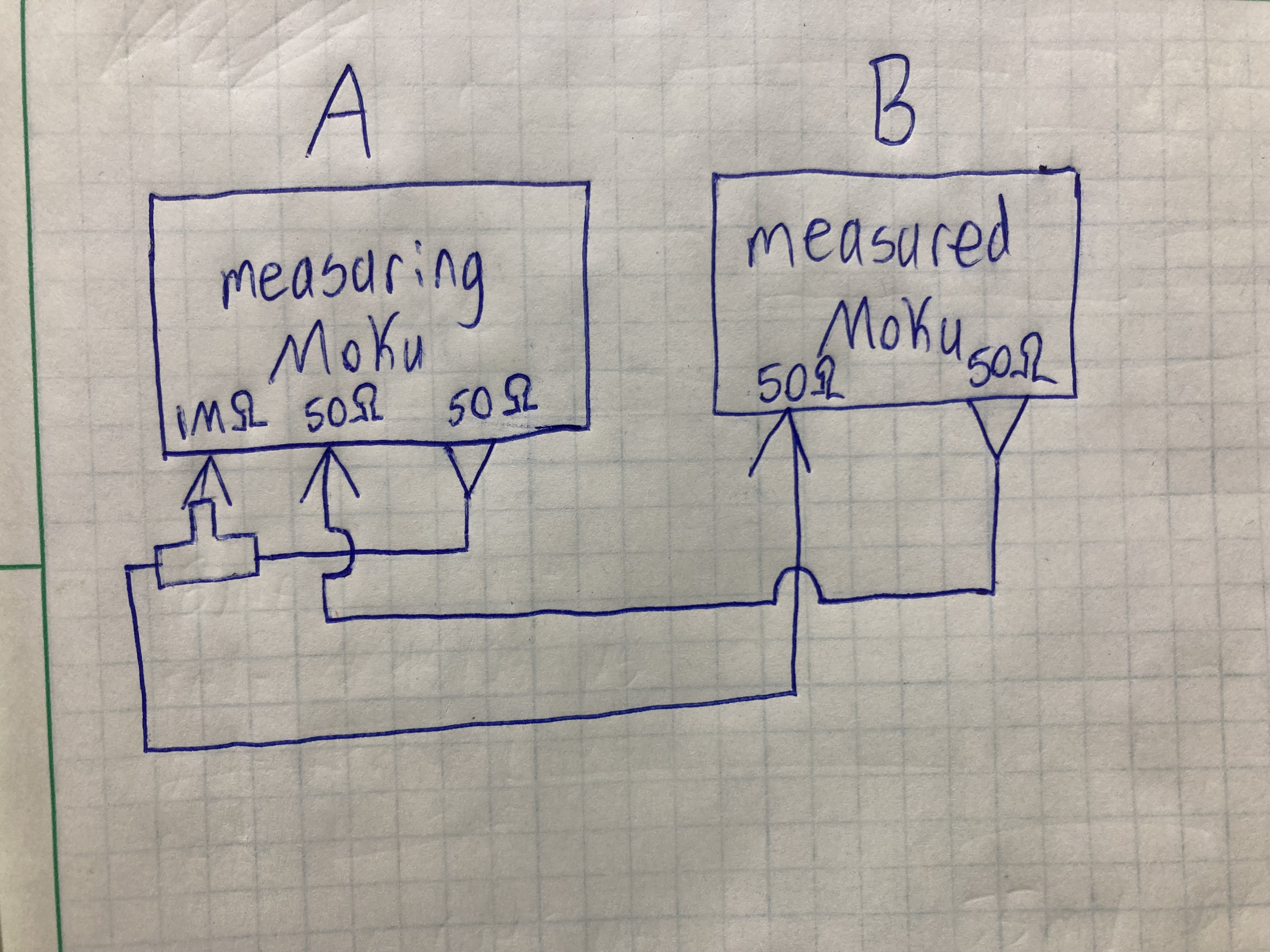
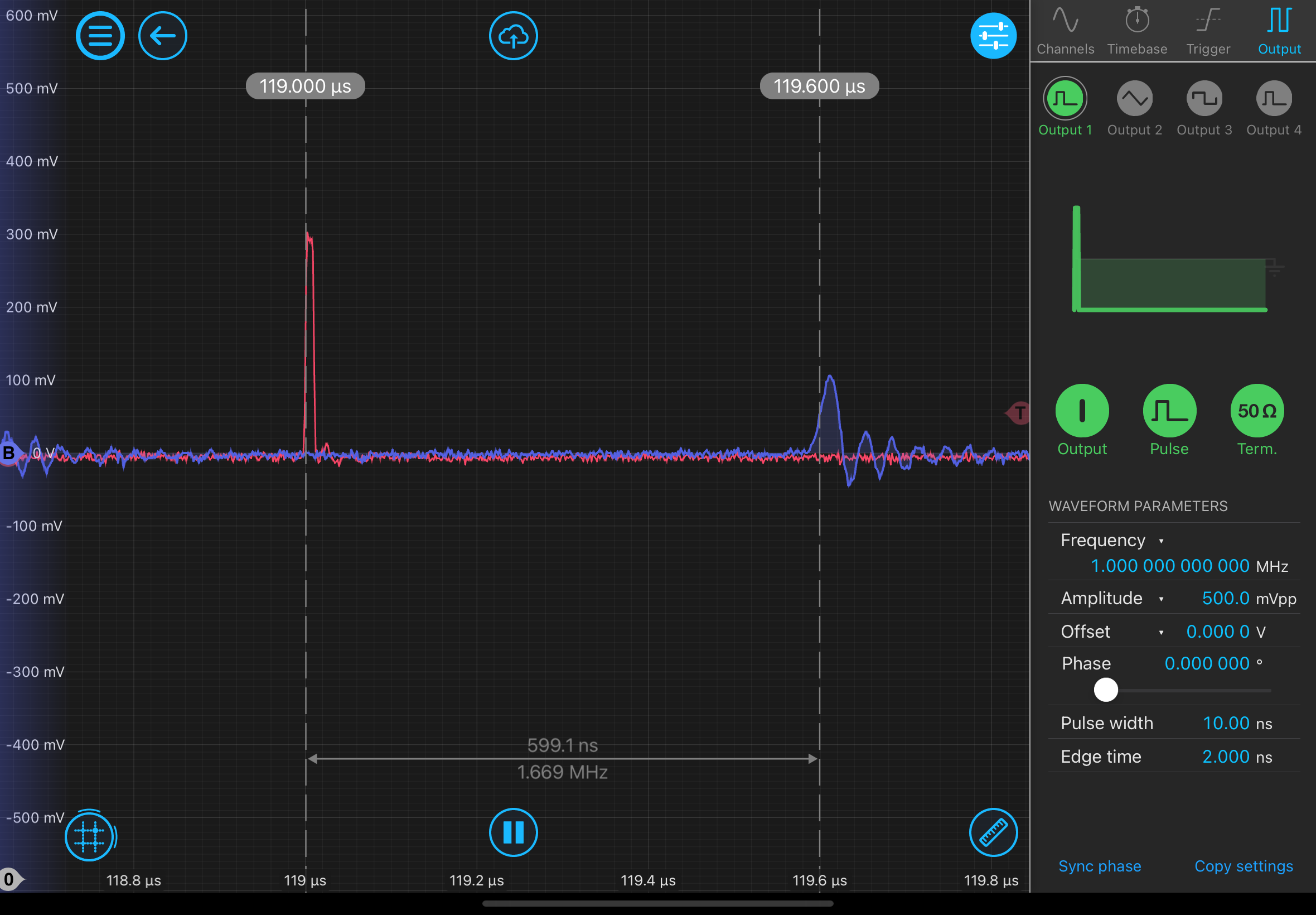
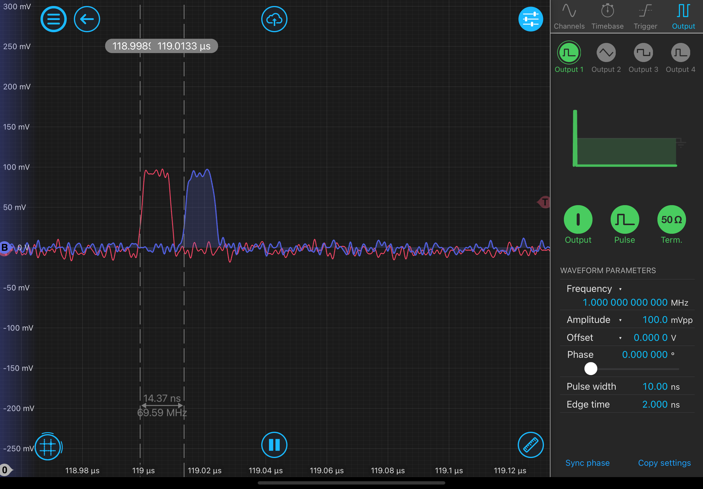
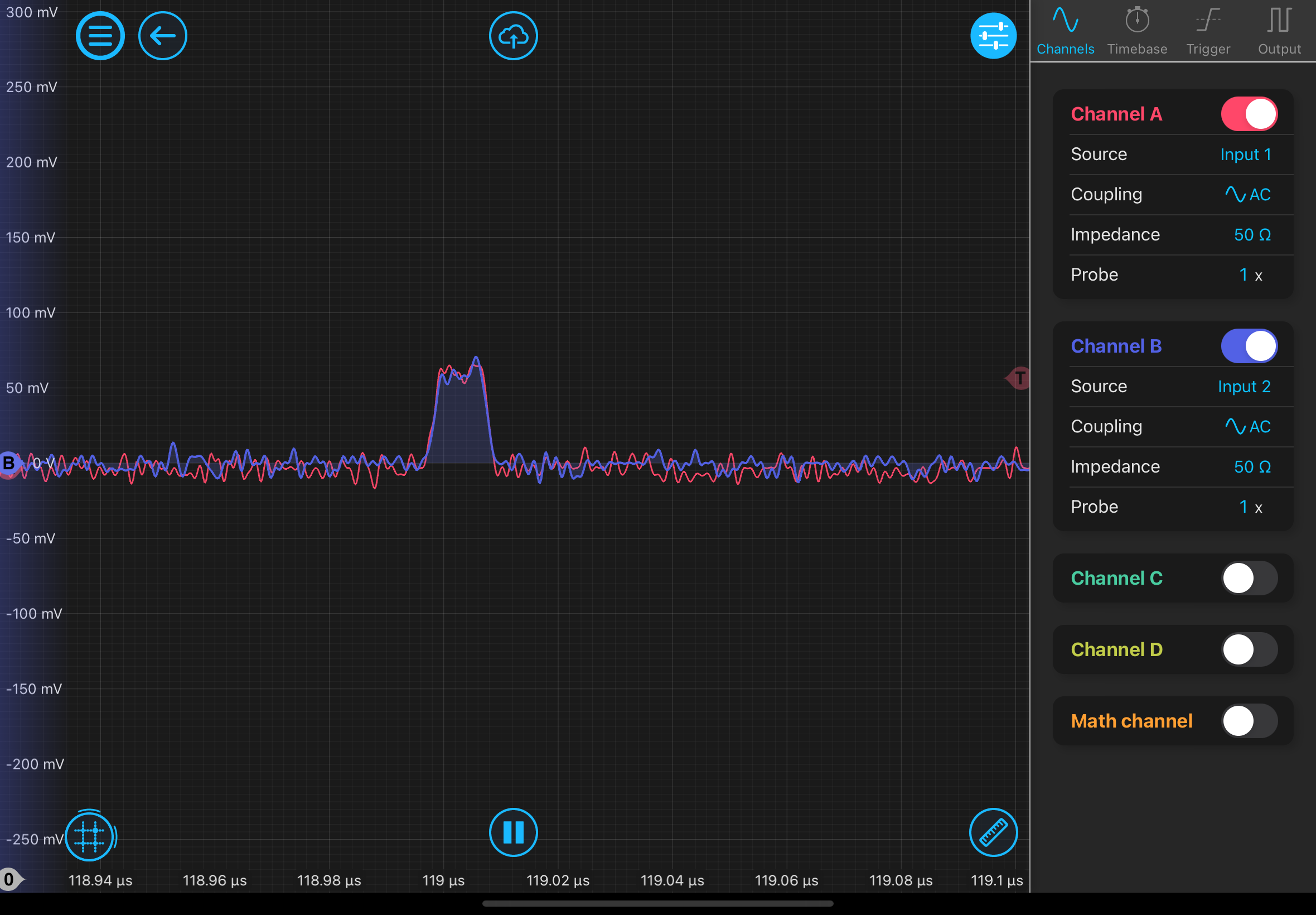
We have performed pulse delay measurements on the various modules of a Moku Pro. This was done using two Moku Pros, the measuring Moku (Moku A) in oscilloscope mode, the measured Moku (Moku B) cycling through the modules. Moku A emits a pulse which is first detected by Moku A before traveling to Moku B where it is processed, and a response is emitted. The response is then measured on a second input of Moku A. See the diagram below. The delay was determined by measuring the distance between the half maxima of the rising edge of each pulse. A 10 ns width pulse was used for all the modules other than the slow path of the Laser Lock Box, which required a 1 microsecond pulse to get an easily measured response pulse. A slightly modified setup was tried where a compensating length of cable was insterted between the BNC T and the first input of Moku A.
| Module | Short T delay (ns) | Long T delay (ns) |
| BNC barrel | 14 | 0 |
| Digital Filter Box | 1200 | 1190 |
| Laser Lock Box fast path | 604 | 600 |
| Laser Lock Box slow path | 5480 | 5443 |
| PID Controller | 527 | 511 |
The FIR filters change their delay based on the number of coefficents. The filter measured is a bandstop with the minum width notch at the maxium frequency, designed to be as close to an all-pass as possible. The "short T" was used
| Coefficents | Delay (ns) |
| 3 | 859 |
| 39 | 1330 |
| 83 | 1890 |
| 145 | 2680 |
| 191 | 3280 |
| 231 | 3800 |