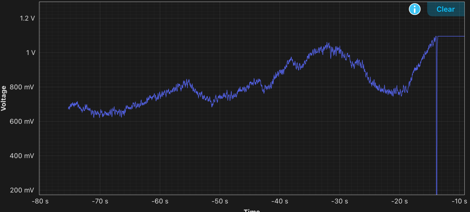
I noticed some drift in the frequency of the laser that may prove to be harmful for the experiment down the road. Untitled.png shows the voltage offset over time of the slow controller output while the cavity is locked. As you can see, it is roughly centered around the middle of its range and drifts out of range eventually losing lock once it goes about its maximum offset of 1V. The change in optical path length the piezo is compensating for is approximately (1.1V - .6 V) * 15 * 3.3e-6 m/150V = 165 nm. This seems like a large amount of drift, but the main problem I think is the output for the controllers in the laser lock box of the moku is limited to 1 V. So we are limited to roughly 10% of the entire 150 V range allowed by the piezo. Although it would work for the demonstrator, I think a reference cavity is out of the question for end design since the two lasers will eventually need to be phase locked to each other.