[Jeff, Ian, Torrey]
With results from 11547 and 11541, we have a calibrated spectrum in m/sqrt(Hz) of the filter cavity. From this calibrated noise spectrum the goal now is design a controller that minimizes the noise when multiplying by the closed loop gain. However, after playing with the moku alot there are a few caviots.
1) Ideally we would upload a custom filter with the desired shape into the low pass filter in the laser lock box. However, the moku requires a text file with the filter described in second order sections (SOS). Most places that you can upload a filter allow up to four rows of SOS to describe your controller. For some reason at only this low pass filter in the laser lock box, it only allows less than 3 (haven't tried 2 rows, but doesn't except 3). This allows us potentially with 4 poles and zeros to describe your optimal filter, which is not ideal.
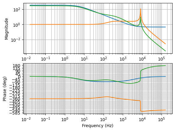
2) The second idea was to upload the full controller in the digital filter box (DFB) where the summing of the excitation signal is used when taking transfer functions. The problem with this is it saturates the scan signal and therefore the output going to the piezo, meaning we can't actuate on the length of cavity. It seems two things saturate this signal: having any amount of gain at DC in the controller and having a positive gain near the resonant frequency, which at the time of this experiment was 8.25 kHz (this may have changed, see future log post). Both of these are problematic, but not being able to have any gain at low frequencies makes this not useable.
In order to get around this, I split the controller up into two parts. The first part is in the fast controller of the lock box, and the second is a filter still uploaded to the DFB, but taking into account that there is some shaping in the laser lock box. So now what this looks like is, we use previous results to design a (more) optimal controller, divide out the shape of the fast controller to get the shape that should be uploaded into the DFB. The idea being that one can lock the cavity with just the laser lock box and then turn on the custom DFB filter as a noise eater, to further improve the quality of lock.
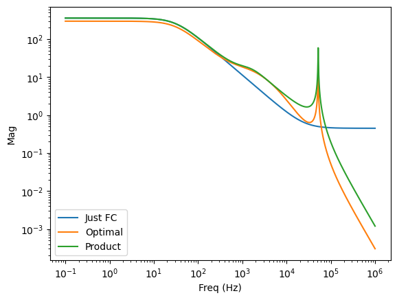
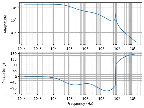
So, for example, if we thought optimalshape.png was our optimal controller, we can find the filter that when doing Fast_Controller * mystery_filter = optimal_shape. optimalproduct.png shows roughly what this looked like. Converting this to SOS and uploading to the moku using Jeff's code makes the cavity lock much worse. My best guess at the moment is that there is a flaw in our understanding of the actual noise in the system, leading to a controller that isn't supressing at the correct frequencies. More investigation is needed.