[Ian, Torrey]
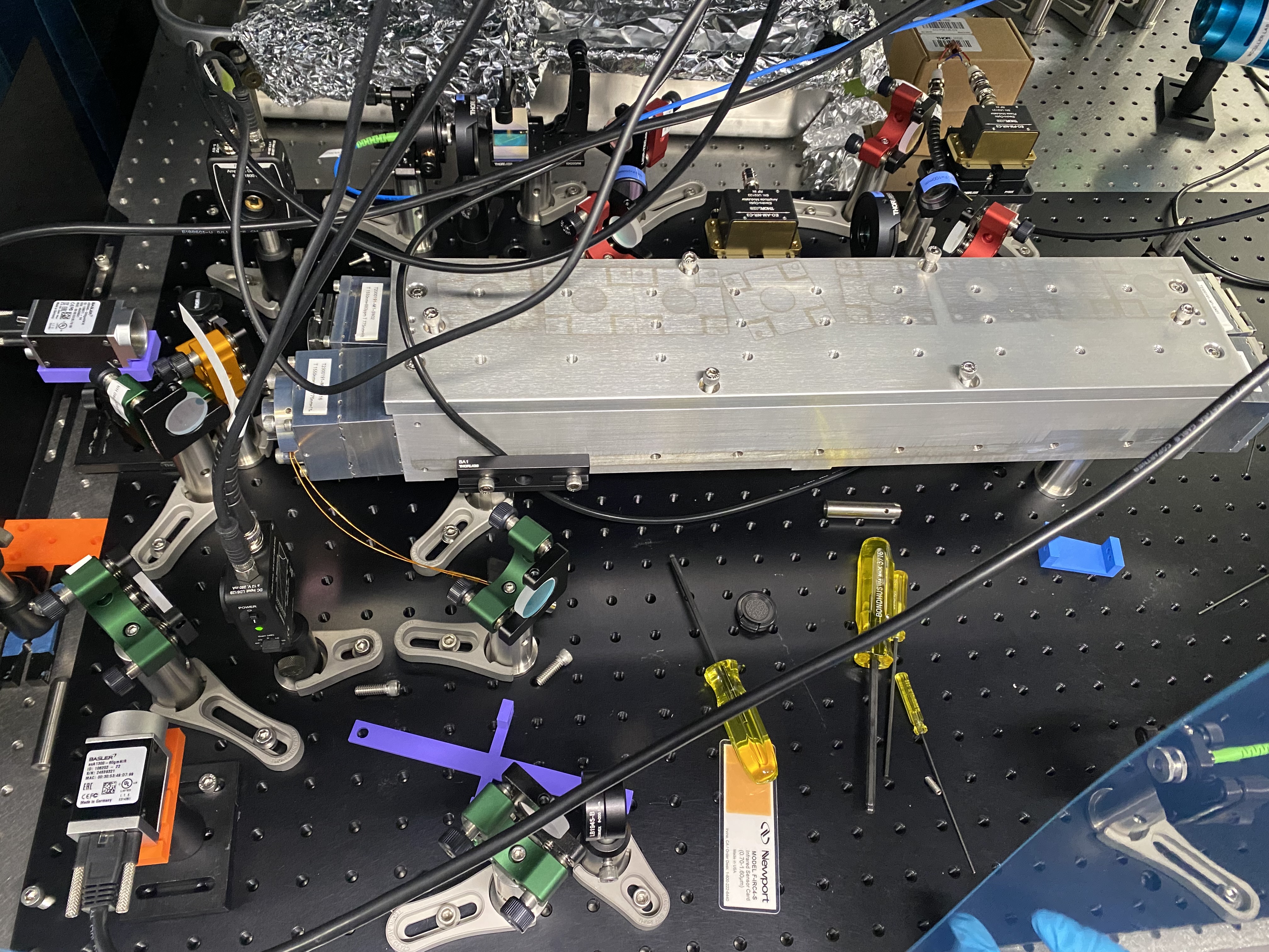
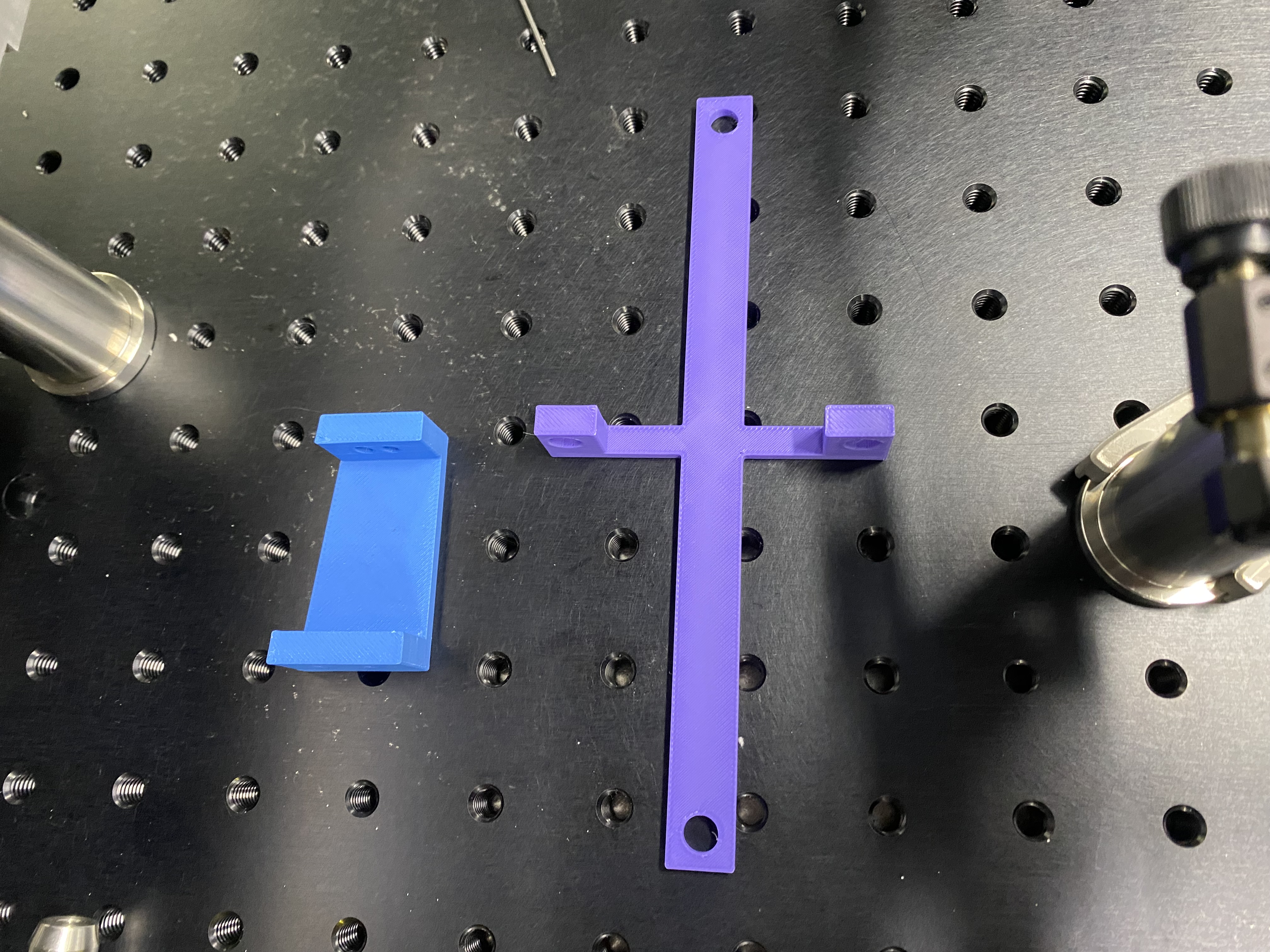
We have aligned the 775nm light path and cavity mirrors to the point that we have a large a mount of 0,0 mode flashing! We did this by first removing the input coupler (OFCM3 see labeled photo in post 11575) from the cavity so we could see the beam inside the cavity without strong reflections. The using the 3D printed jigs to get the beam close to the proper alignment for the other three mirrors. After we had the alignment correct on those we installed the input coupler (OFCM3). Then we walked the beam around by moving the 775 nm input coupling mirror (OFCM3) and the one diagonal from that (OFCM2) until we saw two beams on the transmitted photodiode. Then we continued to walk it until we saw three. making these overlap on the photodiode made use see HOMs. We played with the alignment walking the beam until we saw the lowest order 0,0 mode flashing with the others.
After we saw the first mode flashing we installed a 50/50 beamsplitter on the transmitted path allowing us to use the Bassler camera that we had been using for alignment and installed a transmission photodiode (Thorlabs PDA50B2). This photodiode is only rated to go down to 800 nm but it has enough sensitivity for the basic lock. We will need to replace it when we get new PDs. We also realigned the reflected beam path because that was now off from our alignment.
With all of those fixes and installations of new BNC cables (which we had to make out of a number of shorter ones. we should buy more) we were able to get a rough lock on the 0,0 mode shown in first attached image. We think that there needs to be adjustments to the mode matching to make the lock robust.
Post updated from earlier by Ian