I have calculated the predicted angular and linear deflection from changing the AOM drive frequency.
The setup:
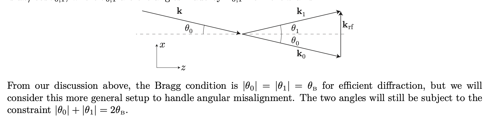
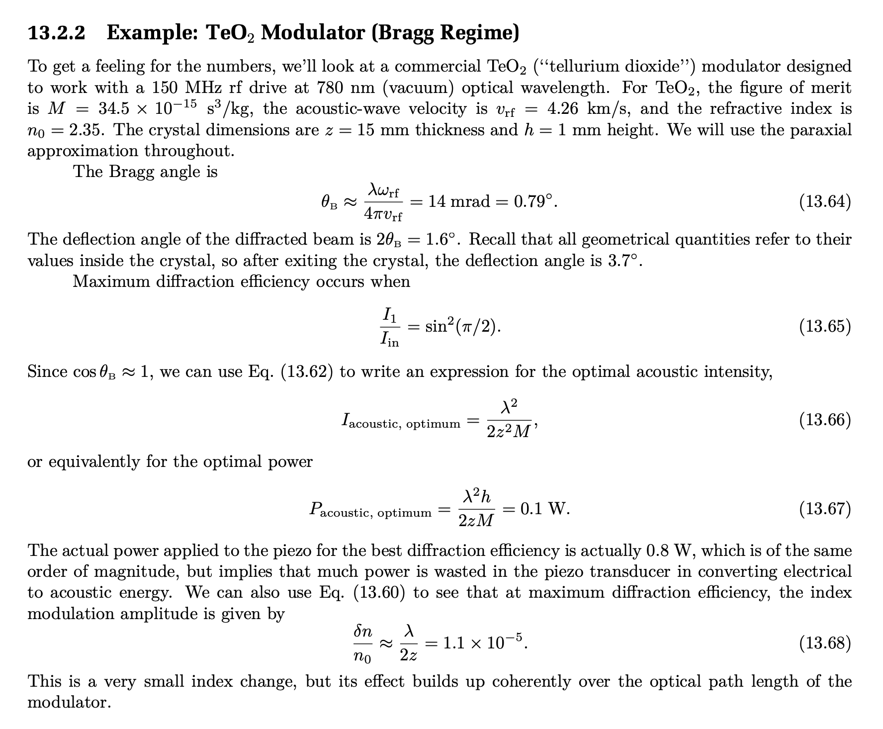
Assume the beam is aligned for some nominal offset frequency such that the angle of incidence on the (thin) crystal is equal to \theta_{B, i} (B for Bragg, i for initial setup). This angle. is linear with frequency. Assume the unshifted beam goes through and is blocked and the frequency shifted beam, which has an angle of 2*\theta_{B, i} with the unshifted beam, is reflected back to the same spot on the crystal. Then assume this beam is either unshifted again, or shifted again (so twice the frequency shift). See the images from Steck's Optics Notes section 13.2.
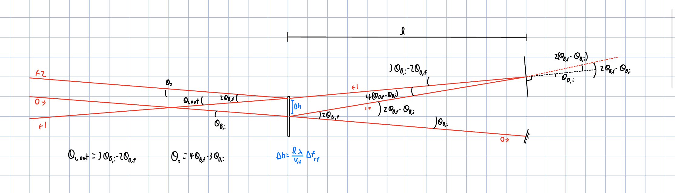
Now assume the rf frequency is changed. Now the shifted beam makes an angle of 2*\theta_{B, f} with the unshifted beam in both directions. Assume nothing else, such as the alignment of the beam incident on the crystal or the alignment of the mirror, has changed. I have calculated the angle of transmission of the once and twice shifted beams. See my sketch attached.
Twice shifted:
\[\theta_2 = 4\theta_{B, f} - 3\theta_{B, i}\]
Once shifted:
\[\theta_{1, \text{out}} = 3\theta_{B, i} - 2\theta_{B, f}\].
So the twice shifted beam is twice as sensitive to the frequency shift. However, the frequency shift required is half, so it does not matter which beam is used.
The linear deflection, for a AOM to mirror distance l = 5 in, a wavelength \lambda = 775 nm, a crystal speed of sound v_{rf} = 4200 m/s, and a frequency shift of 40 MHz.
\[\Delta h = \frac{l \lambda}{v_{rf}}\Delta f_{rf} \approx 1.4 mm\].
There are lots of triangles and some AOM physics that is new to me, so there is a decent change I have messed up somewhere.
We are imaging the beams after they go through a lens, so this might distort the picture presented.