[Daniel,Torrey]
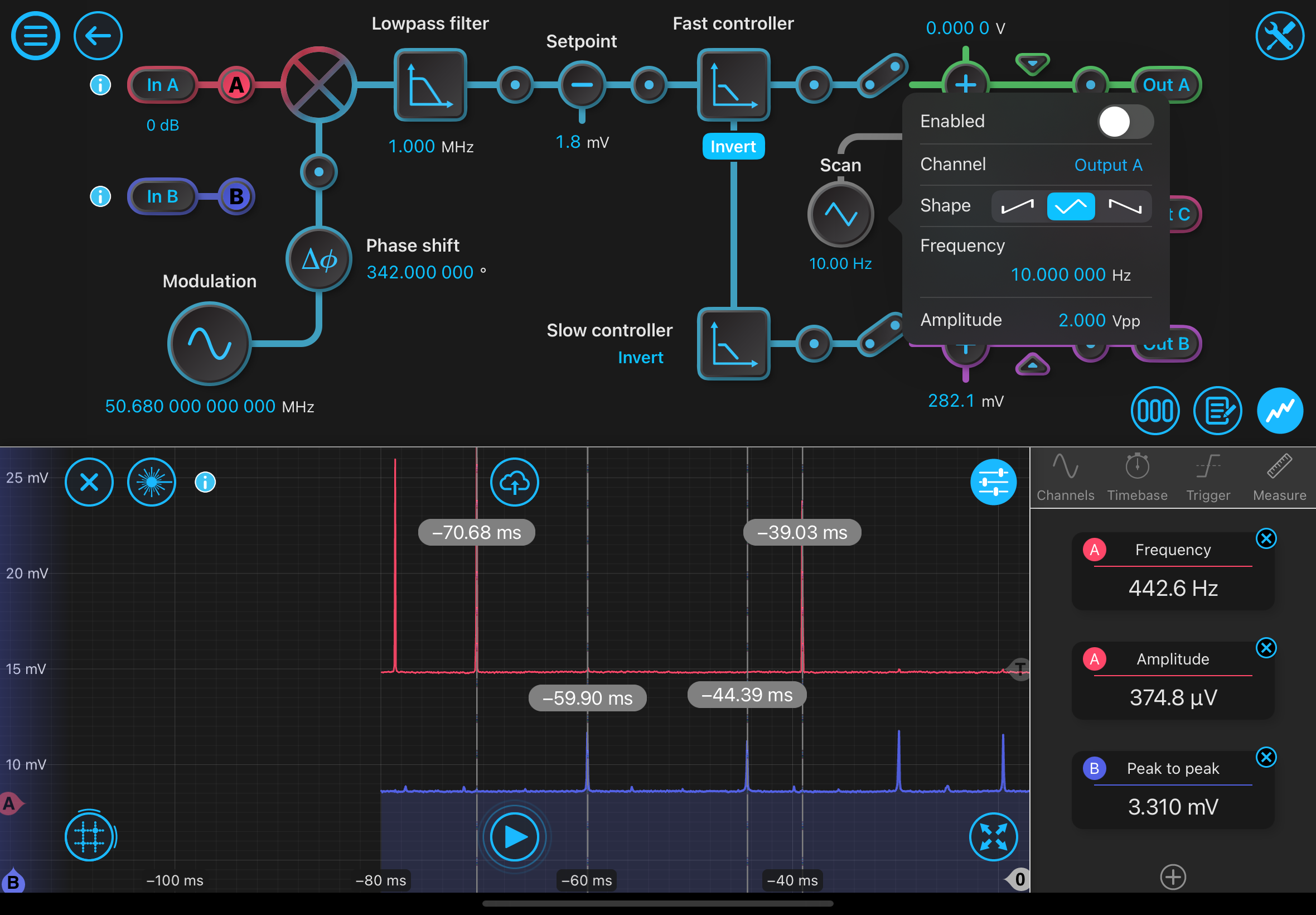
Since we have a frequency shift on the 775 light we need to experimentally determine how far apart the two 0,0 modes are in frequency space. We can do this by using a large scan amplitude (10 HZ triangle wave on laser frequency @ 2 V) to scan over a full FSR in the cavity. This scan shows the transmission peaks from the two different beams arriving at the PDs at different times. We have confirmed these peaks are at distinct voltages.The 4 labelled beams are the two FSRs for each light source. Shifting the AOM drive frequency has the effect of moving the two blue peaks (775 light) left or right, but the spacing between the two peaks remains constant (this is the FSR and is defined by the cavity length). Here, we want to determine how much we should move the frequency of the AOM drive so that one red and one blue peak match up. This can be calculated by just using the fraction of the FSR
\[ redleft = 70.68ms \]
\[ redright = 39.03ms\]
\[ blueleft = 59.90ms\]
\[ blueright = 44.39ms\]
\[ reddiff = redleft - redright\]
\[ bluediff = blueleft - blueright\]
\[ FSR = 125 MHz\]
\[(blueright-redright)/reddiff*FSR/2/1e6) = 10.58 MHz\]
\[(redleft-blueleft)/reddiff*FSR/2/1e6) = 21.28 MHz \]
The 10.58 MHz number is closer, and is to match up the two right peaks, however this means increasing the drive frequency. The current RF source is already at a max in frequency. We could use an alternate RF source like the moku or shift back to 80 - 21.28 = 59.72 MHz. Additionally, naivly one would expect that in one direction the required frequency change would be (80 Mhz *2 - 125 MHz) /2 = 17.5 MHz or . This discrepency comes from additional phase pick up from the coatings on the super optics (the coating depth is many wavelengths deep, so the shift is actually something like in the GHz but you this number would be the remainder after dividing by the FSR).