[Briana, Ian, Torrey]
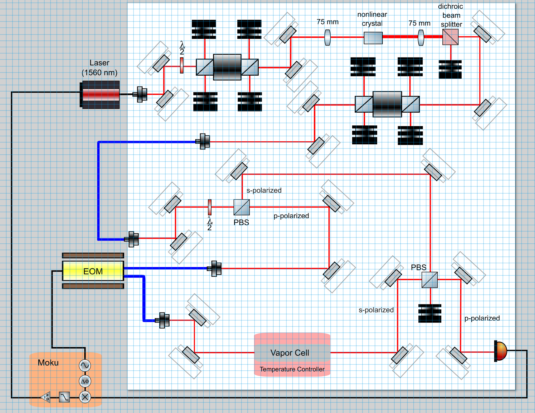
Updated Ian's drawing into a scaled layout with some additional components following Ian and Torrey's comments (attached). The schematic is split into two sections: simple harmonic generation (SHG) for frequency doubling the laser (upper half roughly separated by the first horizontal blue fiber coupling) and the vapor cell locking with counterpropagating beams. The laser, EOM, and Moku elements are not on the breadboard- they will be connected via fiber coupling.
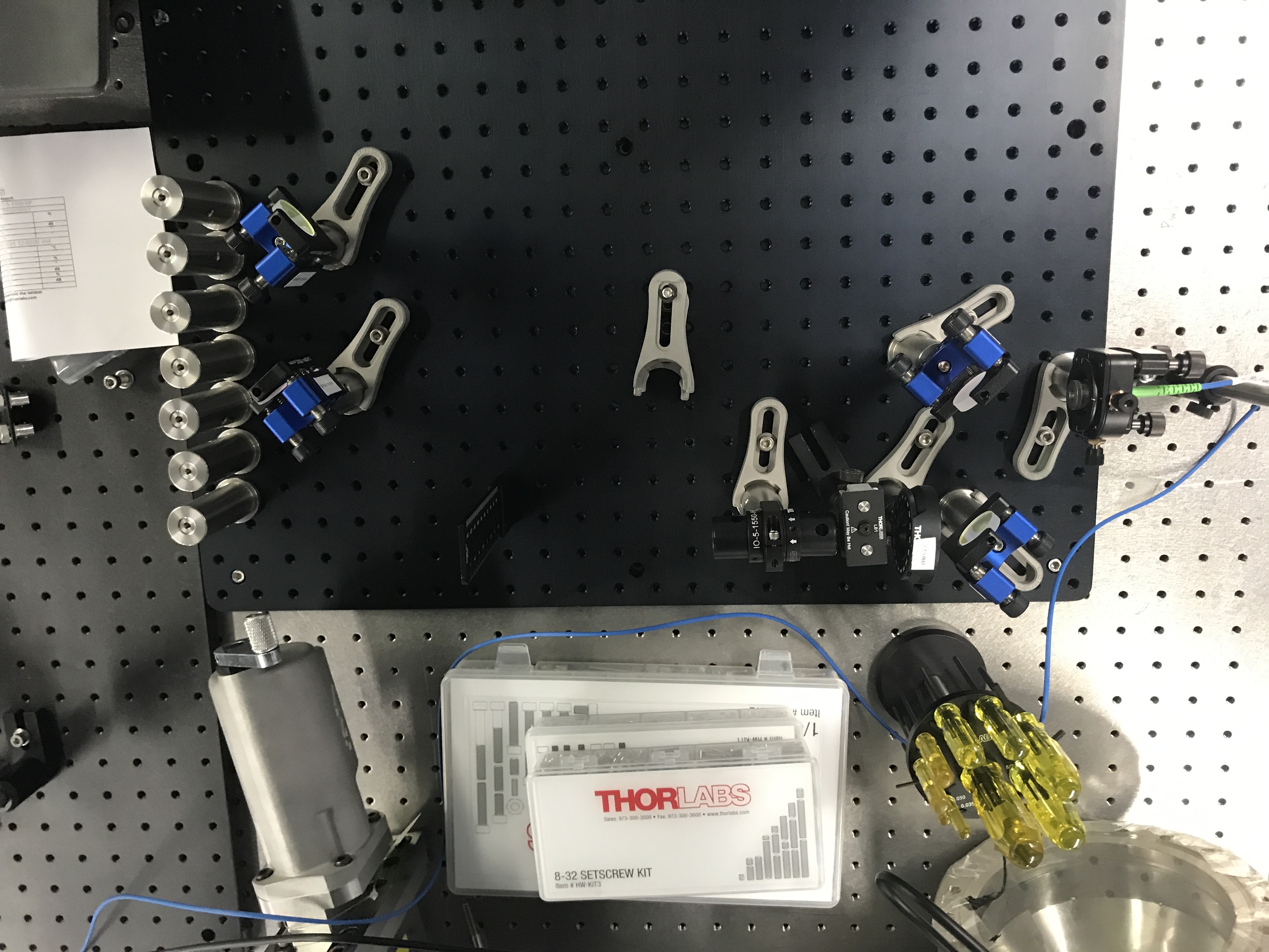
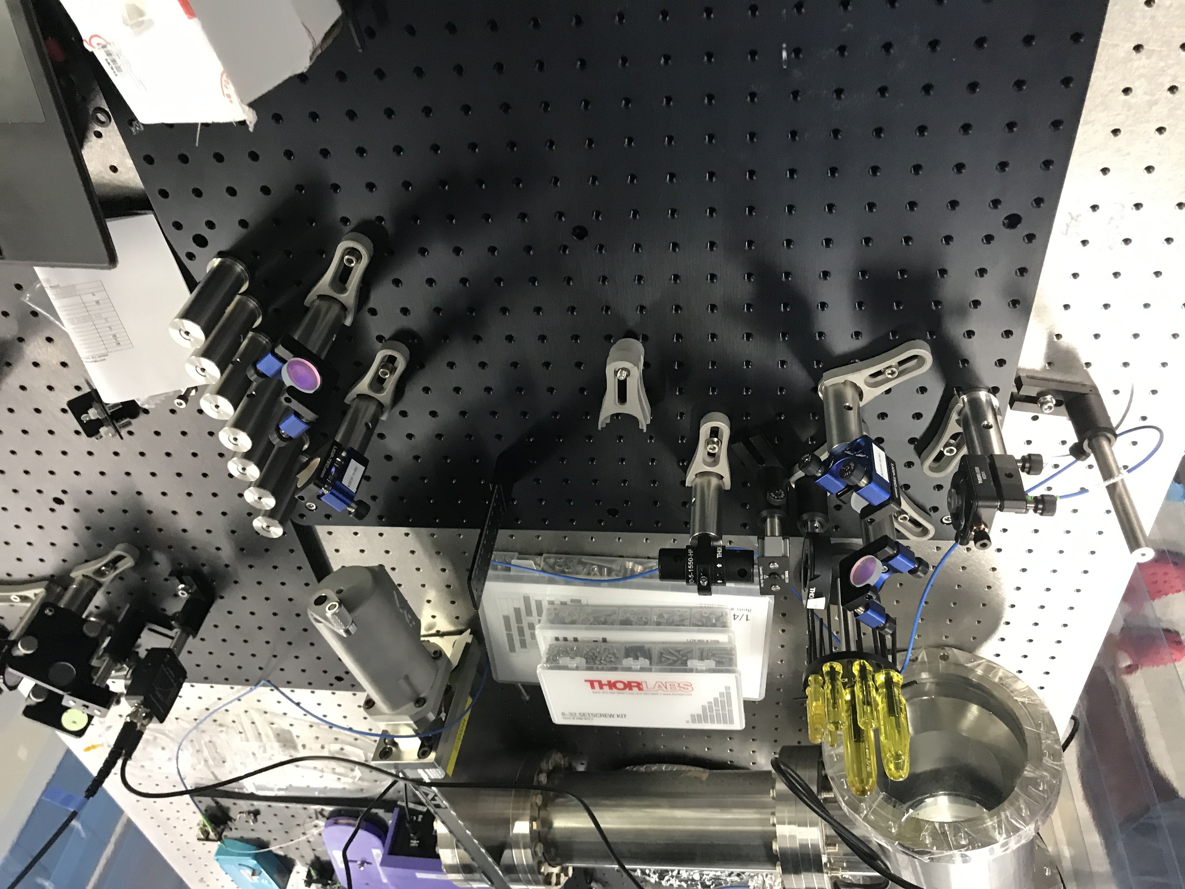
We are currently using the 2 ft by 2 ft black breadboard previously earmarked for LFC. We are keeping it on one board so it can be easily moved to the new lab space. The breadboard is located on the central large table in the corner closest to the tool chest. A vacuum component was moved under the table to make room for the breadboard.
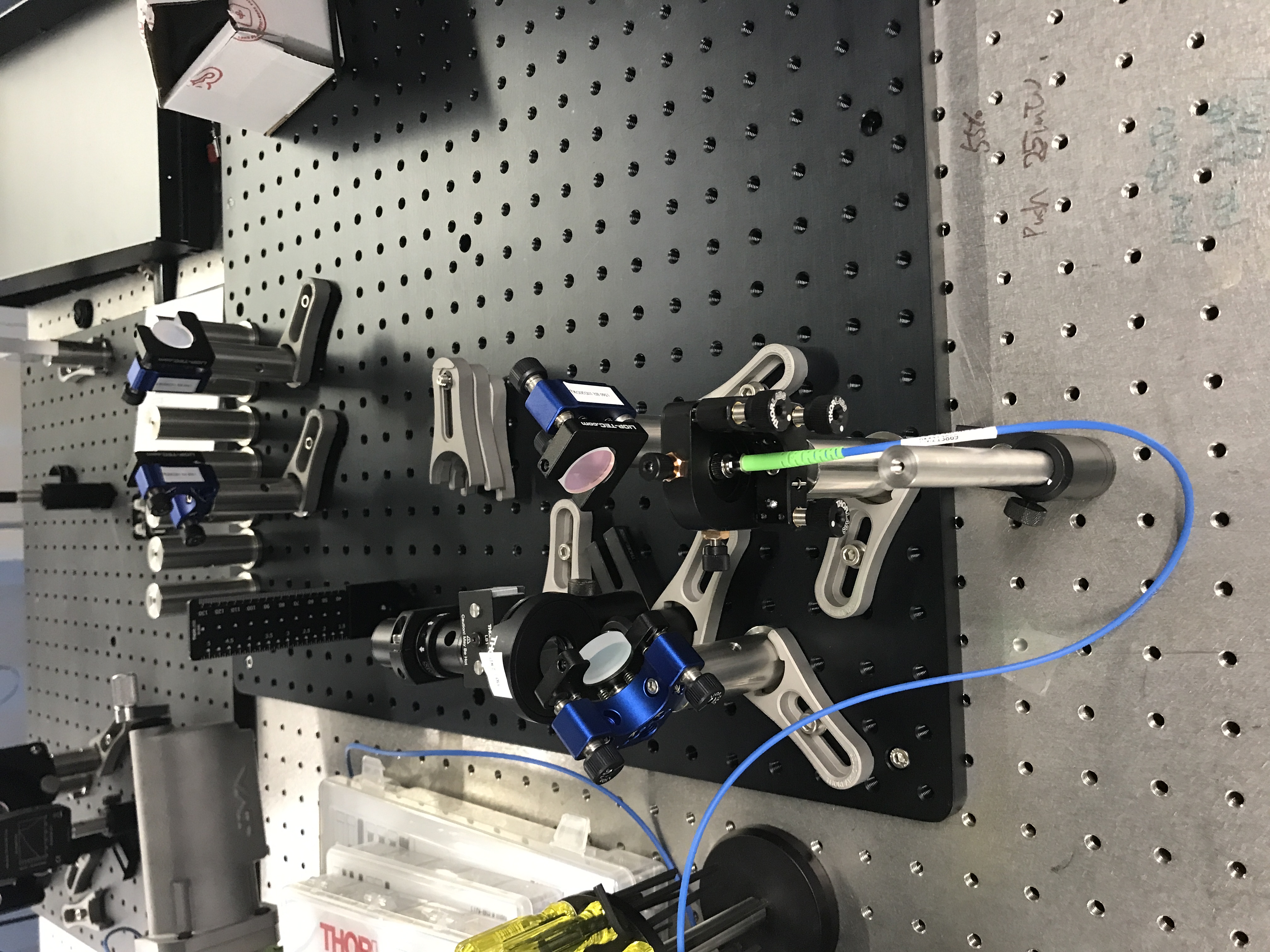
With this set layout, we started building the SHG part using a path off the GQuEST 1550 nm laser to help align the setup. We intend to eventually use the1560 nm laser. The goal of the SHG is to produce a beam with half the wavelength (780 nm). The 4 mirrors used for the 1550 nm SHG setup have blue mounts. We aligned the first two mirrors followed by a half waveplate and the first Faraday isolator. On the other SHG setup in the lab (same table but towards the far wall), a five axis mount was used for the Faraday isolator but we just used a pillar since it was close enough to the beam height above the table (~4 cm).
There was a problem where the light entering the Faraday isolator did not visibly transmit through despite being in the beam path and also, there were two beams coming out of the first beam dump with different polarizations. The latter occurrence may have been some combination of polarization/alignment error, but it's kind of weird that there were two beams (back reflections maybe?). Anyways, we solved the overall issue by rotating the isolator because the unaligned polarizations caused the entire beam to be dumped (the isolator used, IO-5-1550-HP, is polarization dependent). After rotating it, the isolator now transmits light and there is no significantly visible light coming out of the beam dumps. We should be careful though because one of the isolator's beam exits is now angled upwards with high probability of going into your eye. Beam dumps are not in place yet- there is currently one between the isolator and waveplate just for temporary placement. Also, the arrow on the isolator should point in the direction of propagating light (useful resource for alignment: How to Align an Optical Isolator | Thorlabs Insights - YouTube).
Link to the experiment proposal for context: https://dcc.ligo.org/LIGO-T2400157