[Briana, Ian]
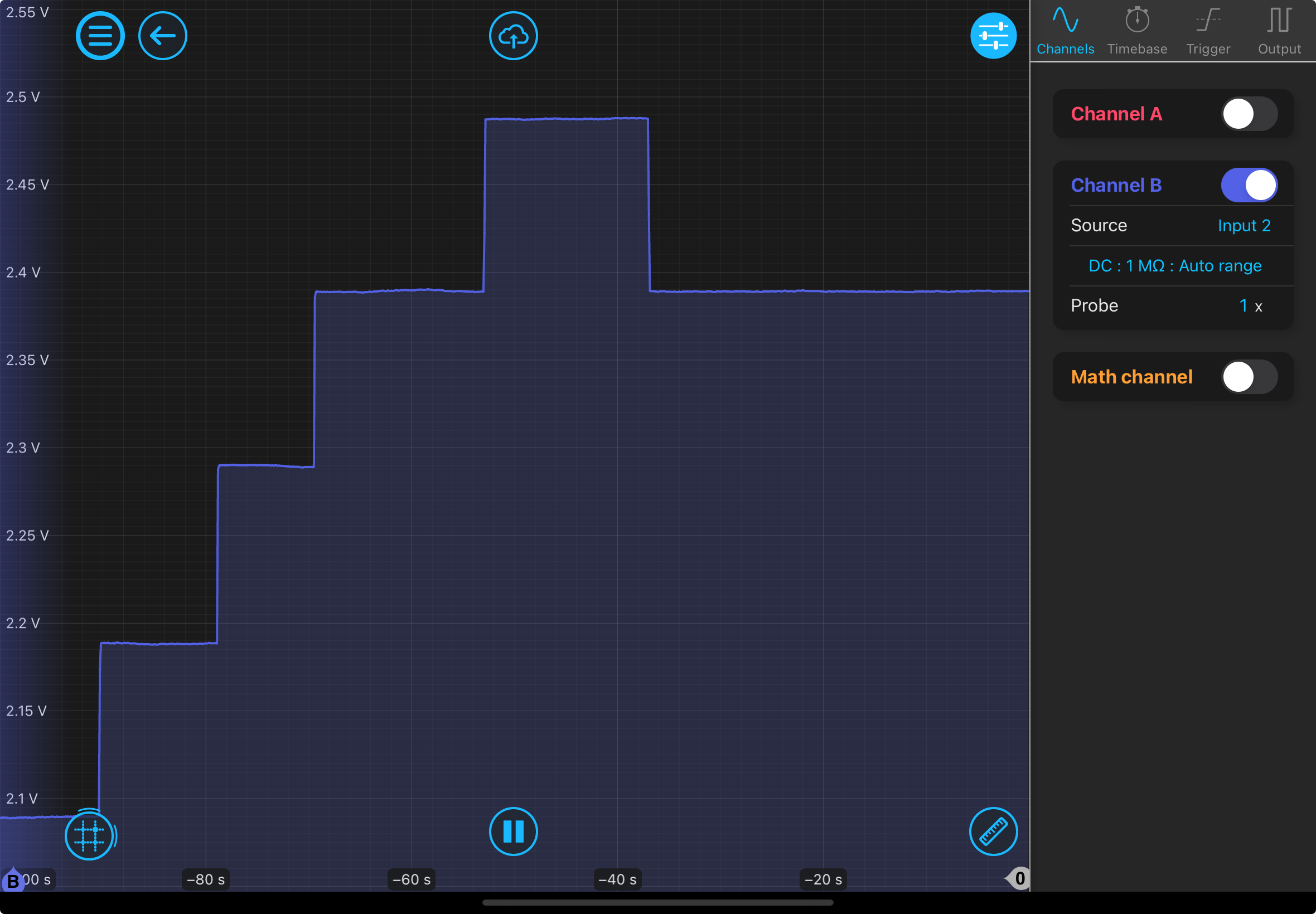
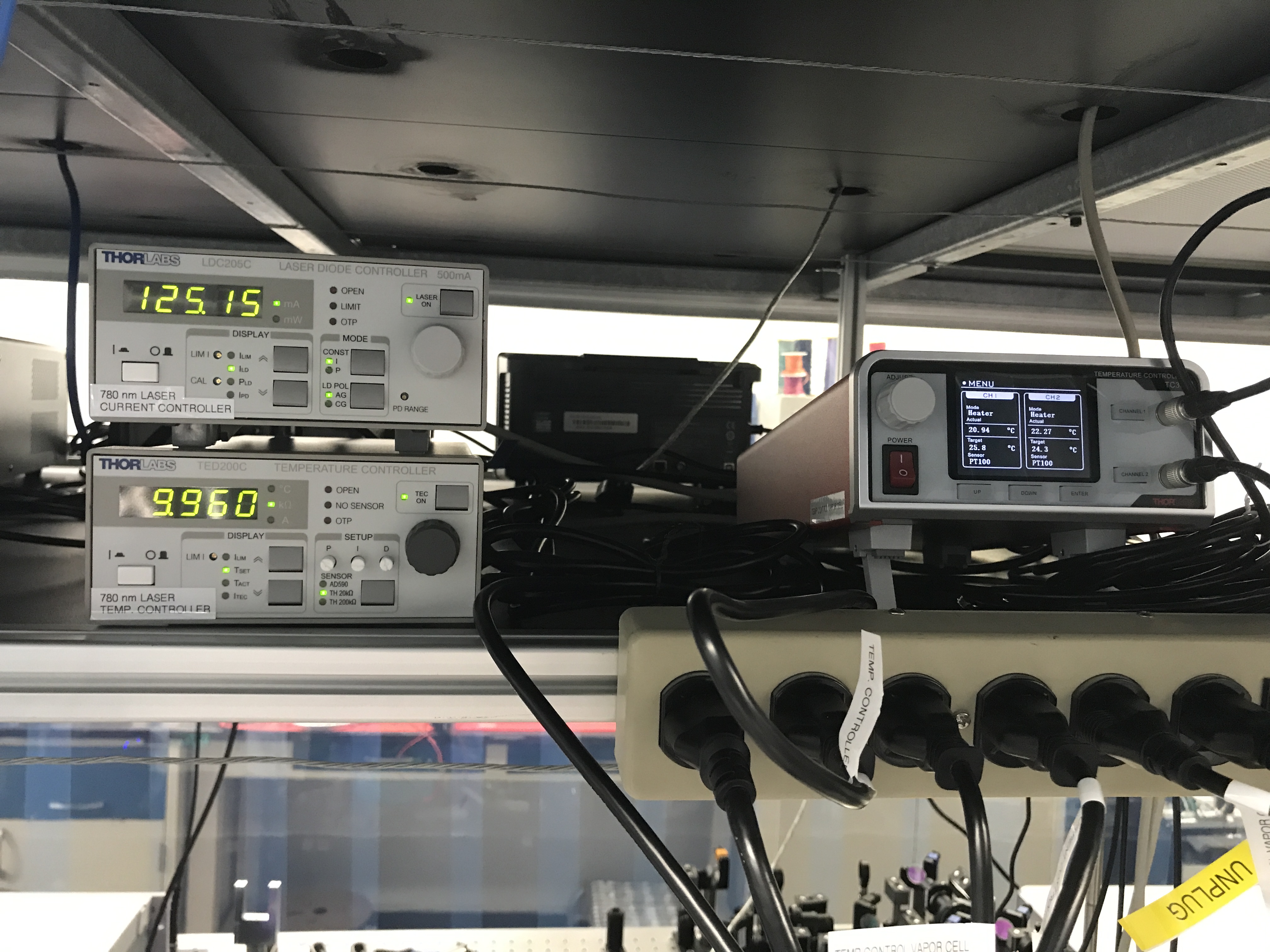
Set up TC300 (vapor cell temperature controller), which is next to the laser controllers. Even though the manual for the TC300 vapor cell temperature controller states that using a 4-wire setting for better accuracy, it does not apply to our thermistor. We should be on the 2-wire setting. If the control isn't applying, make sure the channel buttons are illuminated in green as otherwise they're disabled. Currently having an issue with the discretization of analog temperature output from TC300 as there is only a sharp dip in voltage (corresponding to temperature) when the temperature read reaches an integer (for example, from 23.0 to 22.01 Celsius, the voltage reading is roughly constant and once 22.0 Celsius is reached, the voltage reading drops significantly). See attached picture (temp_ctrl_discrete). I wonder if the 20 Ohm impedance from the analog output needs to be matched by the impedance BNC cable connecting to it. I will also try expanding the temperature range as the voltage drop is equal to the 5V spanned by the analog output divided by the set temperature range (0-50 Celsius), so maybe that has an effect. This range was chosen because the heater assembly should not exceed 50 deg Celsius. Either way, will need to fix this before tuning PID controllers of the TC300.
We moved the bottom Moku Pro (not connected to anything) on the rack near the main computer in place of where the Moku Go was. Moku Go has been returned to original cabinet. Both channels of the vapor cell temperature controller (labelled Aliyah Boston and Angel Reese) have been connected to the Moku input. Photodetector connected to Moku input is labelled Caitlin Clark. Moku output (connected to laser temperature controller input) is labelled Joey Votto.
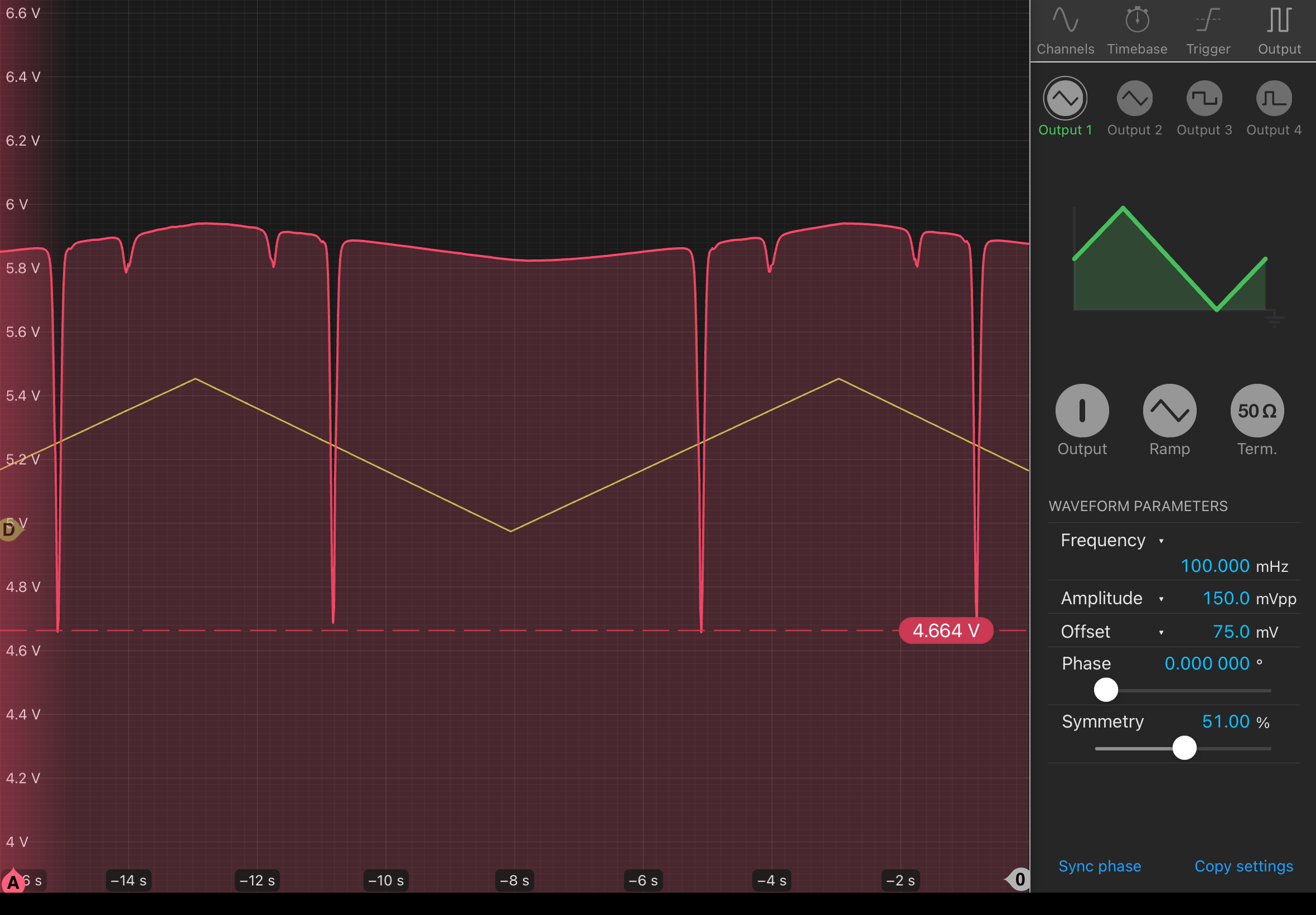
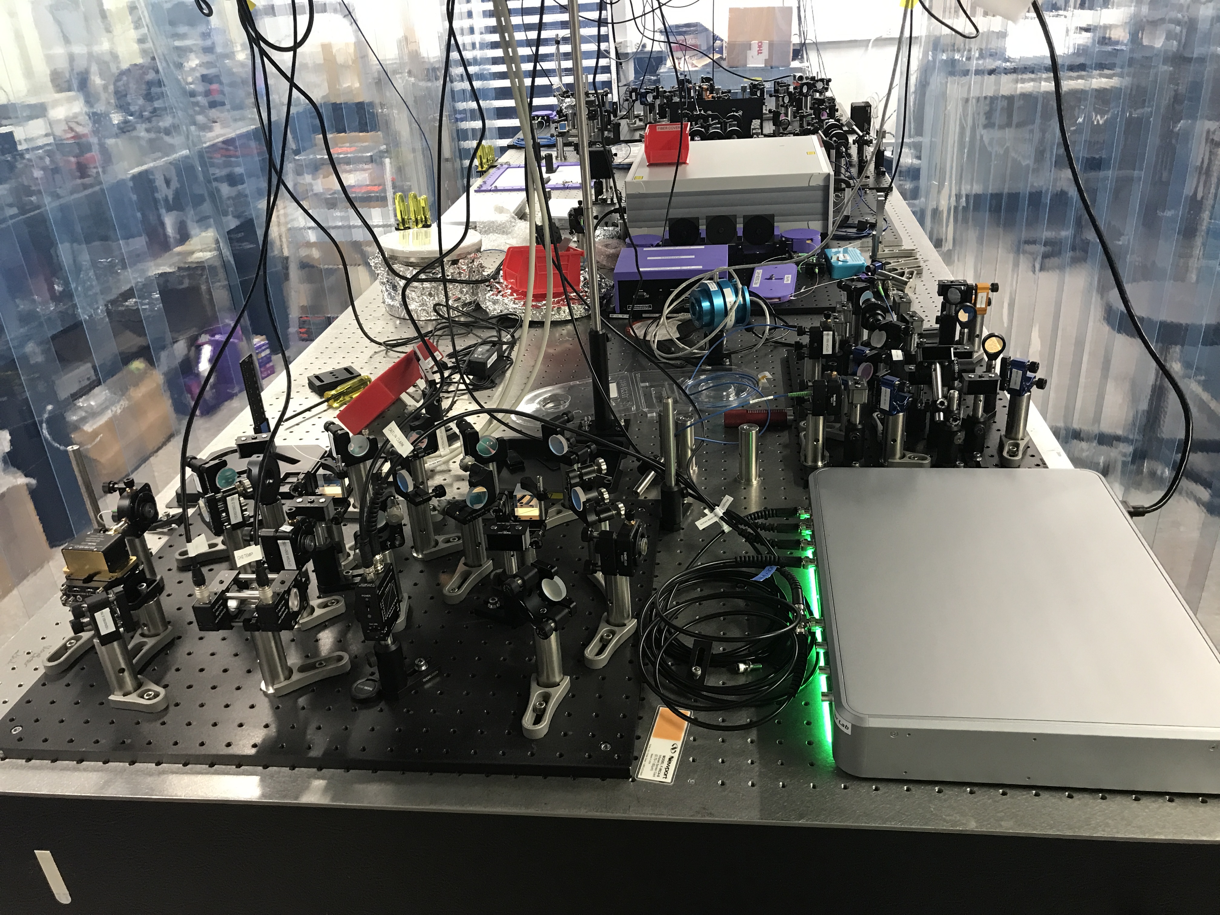
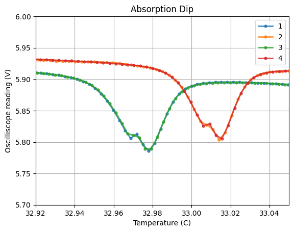
We repeated the measurements last post with the current controller set. We set the laser current controller at 125.08 mA, laser temperature controller scanning from 6.871 - 7.160 kOhms (32.8 - 33.78 Celsius), and the temperature setting on the vapor cell to 45 degrees Celsius on both controllers. Current limit is 0.7 A. We see two dips, one small and one large. The large one likely corresponds to the 780 nm transition, but maybe there is some hyperfine structure causing the smaller dip. We can determine the temperature at which these peaks occur and then, using laser specs, the wavelength, which we can then use to deduce the transition (need to call Thorlabs to ask for the data since it's specific to our laser). I have not figured out why there is a shift between the trials- it corresponds to the dips on the signal downfall (groups 2 and 4) but not sure why since the signal is the same at these points. If you zoom in onto the smaller dip, you see two overlapping profiles, potentially from two closely spaced transitions. Will determine what wavelengths these correspond to after getting Thorlabs data. Also, previously when we measured the absorption, we had a laser current of around 203 mA, so it was probably saturating the photodetector.
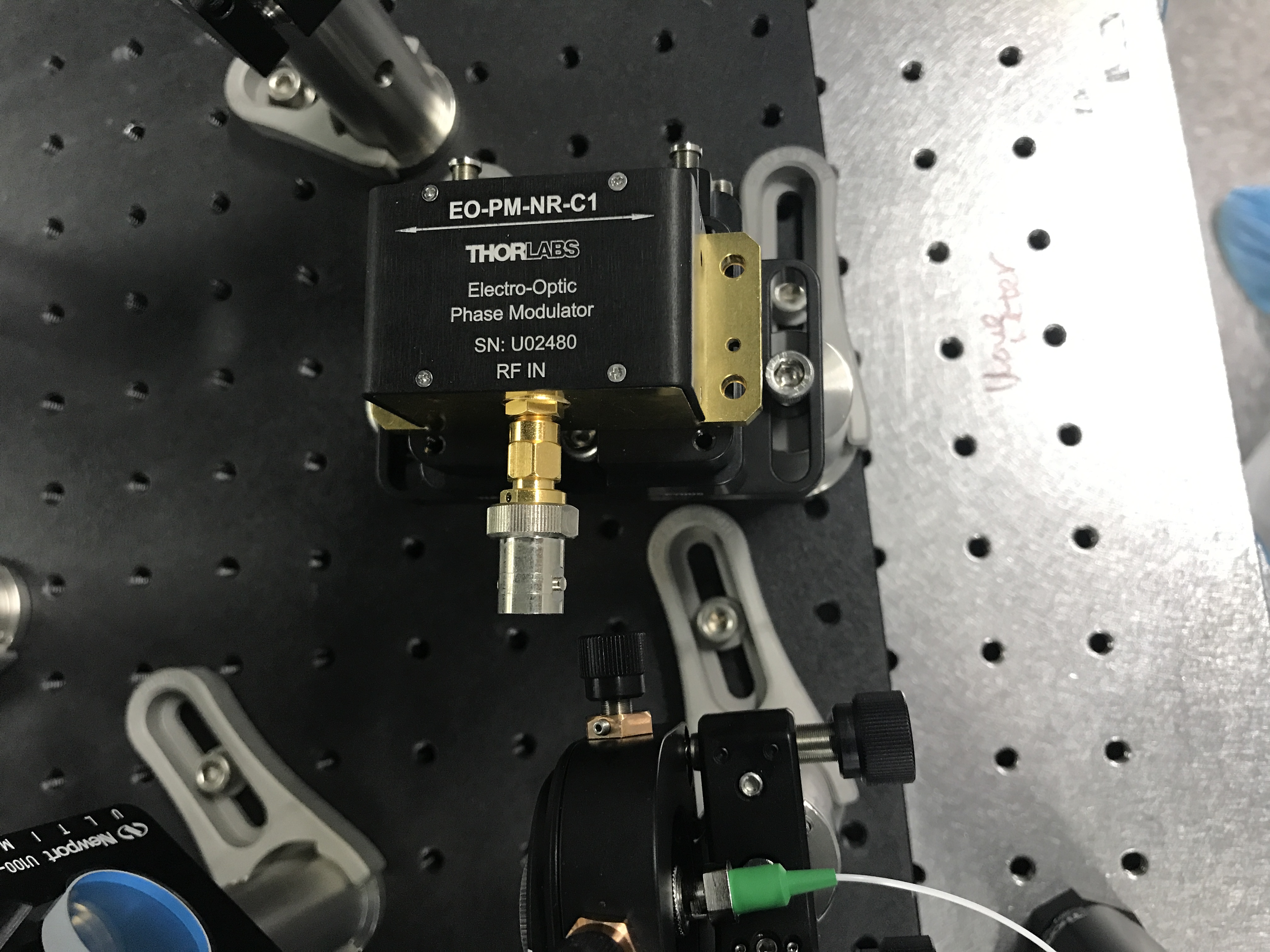
We mounted and placed the EOM (EO-PM-NR-C1) on the vapor cell setup board. Attached is the scanned sheet it came with and the new schematic since the EOM is now free space (need an additional 780 mirror). We will need lenses for focusing the beam down to the 2mm aperture and possibly a waveplate to make sure the input beam is vertically polarized. Also learned to make BNC cables (https://wiki.mccullerlab.com/DCC/T2400001).


Based on the laser specs found here, the spacing between the peaks matches the Rb87 data found here to ~10%.