[Briana, Ian, Torrey]
Sent light through the EOM and measured the spectrum with the spectrum analyzer on the Moku. The EOM phase modulator will phase shift a linearly polarized beam (vertically, along crystal's z axis). The SMA connects to a BNC connector and you can apply a voltage input, changing the extraordinary index of refraction of the crystals inside the modulator. This produces phase shifts. To ensure the polarization doesn't change through the EOM, we need to make sure the input is linearly polarized along this z axis (extraordinary axis). If orthogonal to vertical, there will be less efficiency. Otherwise, you will get some other polarization. We will need a 780 half waveplate (none in the lab so probably needs to be ordered) to be placed before the EOM to obtain the linear z polarization. Also, I think Ian has ordered another 780 polarizing beamsplitter because we need it for our setup.
A 50 Ohm attenuator should be placed when connecting the output signal to the input signal of the Moku for the Moku's safety. We applied a sine signal of frequency 80 MHz to the EOM and saw the sidebands "measured" by the photodetector on the Moku. To get reasonable strong sidebands, the depth of modulation needs to be a certain depth (power should be ~2 Vpp with an additional 14 dB amplification, and the maximum RF power is 35 Vpp, corresponding to 3 W). There are many issues. The oscilloscope reading reaches 2 V in the single oscilloscope mode on the Moku but only reaches 300 mV on the multi instrument oscilloscope mode despite the settings being the same. Clearly, they are not. The photodetector signal is also somehow flat on the multi-instrument mode. I feel this is some confusion with the wires and some Moku settings so will troubleshoot this.
When we look at the spectrum analyzer and apply a voltage across the EOM, we expect to see the sideband signal in the photodetector reading at the modulation frequency. This is more apparent at certain modulation frequencies, so we can tune this to see what works best. We put the vapor cell in place to see if an error signal appeared but it's very faint. Need to optimize dip depth and fix all these issues before we can really assess the supposed error signal.
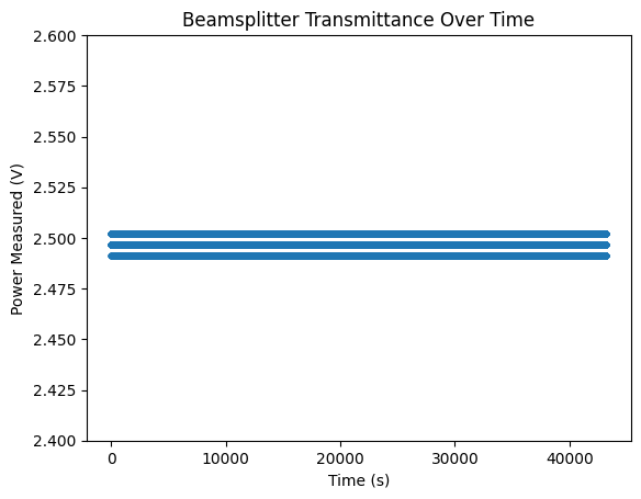
Will try and turn the laser fiber/collimator output and see if polarization changes to address the polarization drift problem, since the fiber keys are aligned along the slow axis. It is not obvious to me how this can fix the problem with the polarization (the laser input is what needs to be aligned with the slow axis for the polarization maintaining fiber, not the output) but trying it and seeing if it makes a difference seems reasonable. Also, settings were wrong for yesterday's overnight measurement because rushed to get food, so it looks weirdly discrete again: overnight_polarization_higher_temp_current_fail.png. Will redo correctly.