[Briana, Ian]
Finished mounting mirrors and placing items on breadboard for the pump path, not aligned yet until we can figure out how to take sufficient data for just the probe. We will probably use irises to align the pump and probe when the time comes.
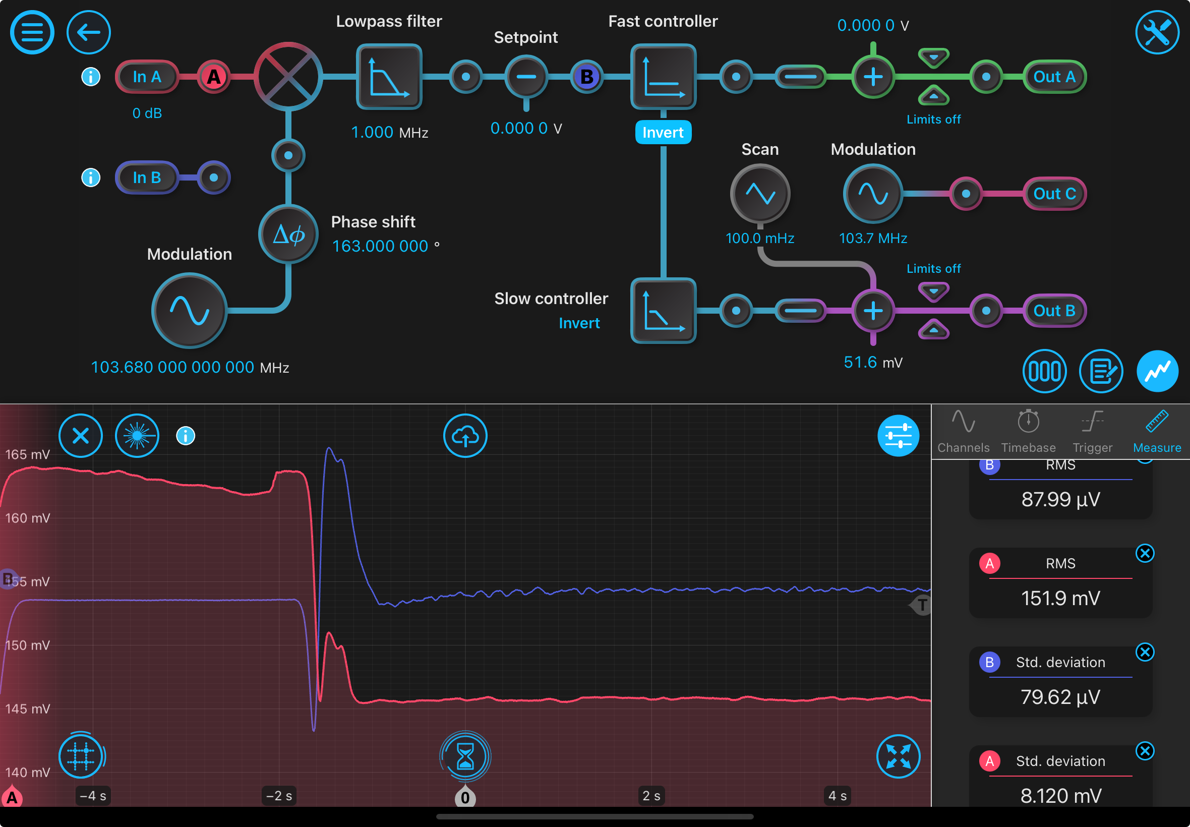
To extract the frequency noise in the system, we need the data of the error signal that we are locking to, the absorption dip (corresponding to the locking signal), and the ramp signal we are sending in. The ramp signal is used to convert to temperature and subsequently to wavelength, which can be used to find linewidth and the values of the error signal at some wavelength away from resonance. Once you get this, you can take measurements of the error signal when the laser is locked to get the amount of frequency drift/noise.
However, the Moku Pro multi-instrument mode can only produce outputs from 2 channels. We took out the Moku Go #2 so you can input two of the three signals and overlay them over the signals from the Moku Pro to match the temperature. This "increases" the number of channels you can measure. In the laser lock assist mode, you would not need three signals because it converts the x axis to the scanning voltage, which would eliminate the need for the ramp signal. However, you seemingly cannot export this data with the x-axis of voltage (see this image for what you see in laser lock assist mode: 2024-08-0217-48-39-0.png). If you can fit to the error signal and extract the linewidth parameter, you could get away with just two signals and not have to undergo the following issues, but that again does not rely on data so it's not ideal anyways.
I would take measurements with the single-instrument mode of the laser lock box but that gives a much weaker error signal (amplitude maybe 50 microvolts compared to the 300 microvolts in multi-instrument mode). I haven't figured out why- it could be that I am missing a setting although I'm pretty sure I have everything the same as multi-instrument mode.
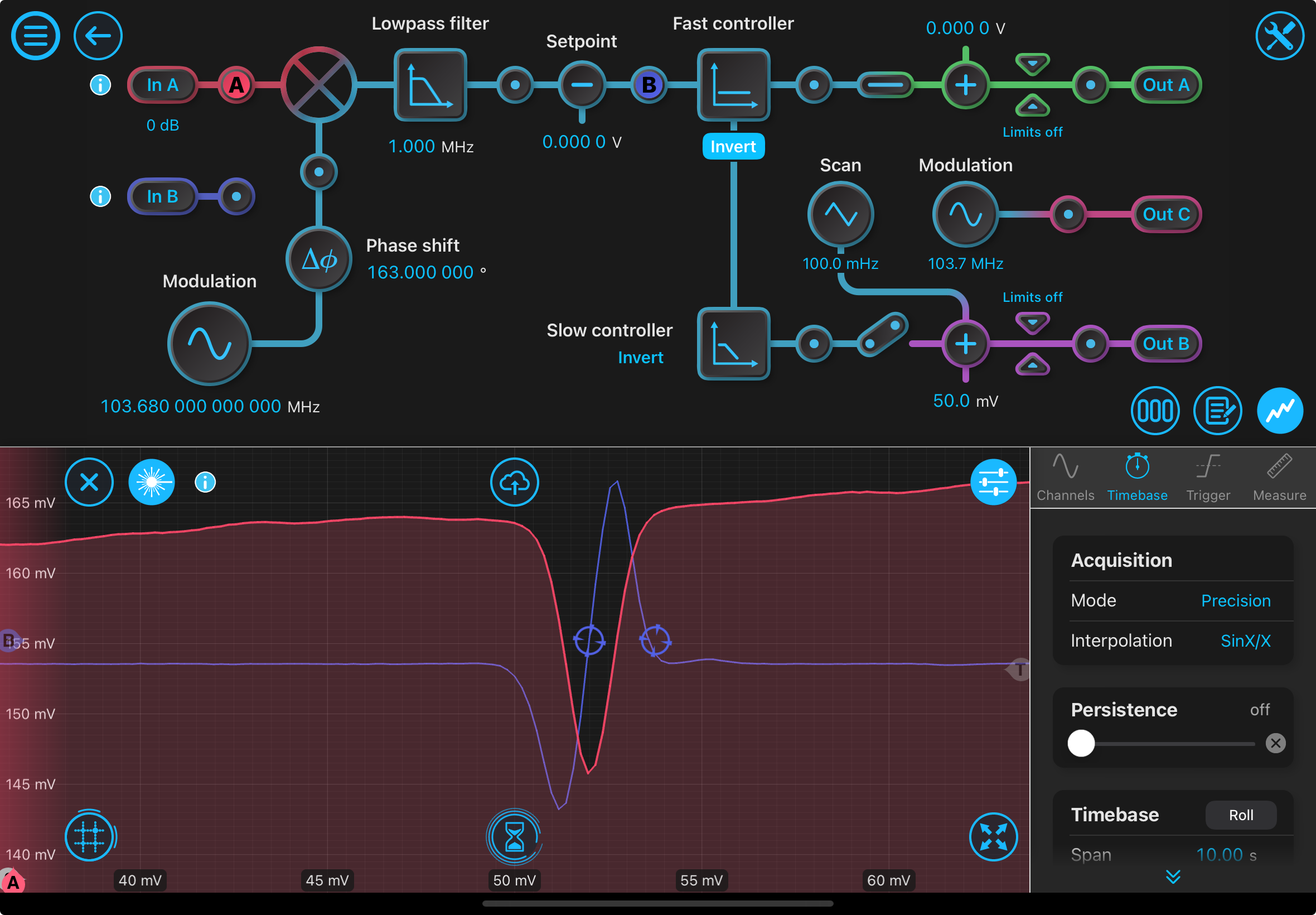
Also locked with the slow controller after setting the fast controller to a gain of 0 and switching outputs: 2024-08-0217-49-25-0.png.
One question I have is whether or not we need a Faraday isolator in the vapor cell setup. Because we have a half waveplate in front of the EOM to maximize efficiency, when the pump comes out of the EOM and back up to the beamsplitter (which would theoretically dump s-polarized light), the light may not be s-polarized so it may not actually get dumped. In this case, putting a Faraday isolator would prevent this light from going into the laser.
All lasers, heaters have been turned off (including 780 nm lasers) and the light saying the laser is on is turned off.