[Briana, Ian, Torrey]
In my previous post(s), I was taking the noise spectrum of the photodetector signal. I should be taking the noise spectrum of the error signal because 1). the error signal tells you how much the laser is actually drifted and 2). the photodetector signal includes additional effects from the EOM modulation.
Controller
The reason why there is no distinction of noise between the unlocked/locked case at high frequencies is that we are controlling the laser frequency by changing temperature, which is a slow actuator. If we can apply the fast controller to an EOM, we can adjust the frequency of the laser through this phase modulation, adding a fast actuator to our slow (temperature) actuator. Also, there is tradeoff with the gain of the controller. If the gain is too high, your system will be stabilized but there will be a lot of noise. If the gain is too low, then your controller won't be doing anything. Essentially, the gain parameters need to be just right so that the noise spectrum doesn't become amplified. Although useful for stabilization, we are not using the derivative control at all in the slow PID controller because this is a rapidly changing system, so we want the controller to be responsive to those changes.
Unfortunate noise spectra
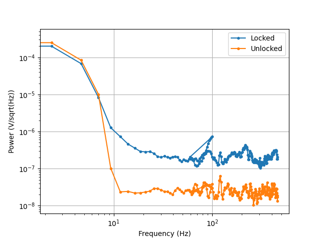
At low frequencies, the noise from the locked laser is lower than that from the not locked. At higher frequencies, the locked laser is noisier than the not locked laser. However, I would expect that because of the higher RMS and standard deviation of the error signal when unlocked, the noise should be higher for the unlocked, so it is not clear to me why it is behaving like this. This has been the case for different controllers at unity gain frequencies from 3 Hz to a few hundred Hz. An example of this is using locked5 data (see Nextcloud Users/briana/8_9_2024: LockedUnlockedNoiseSpectra.png with the following controller.
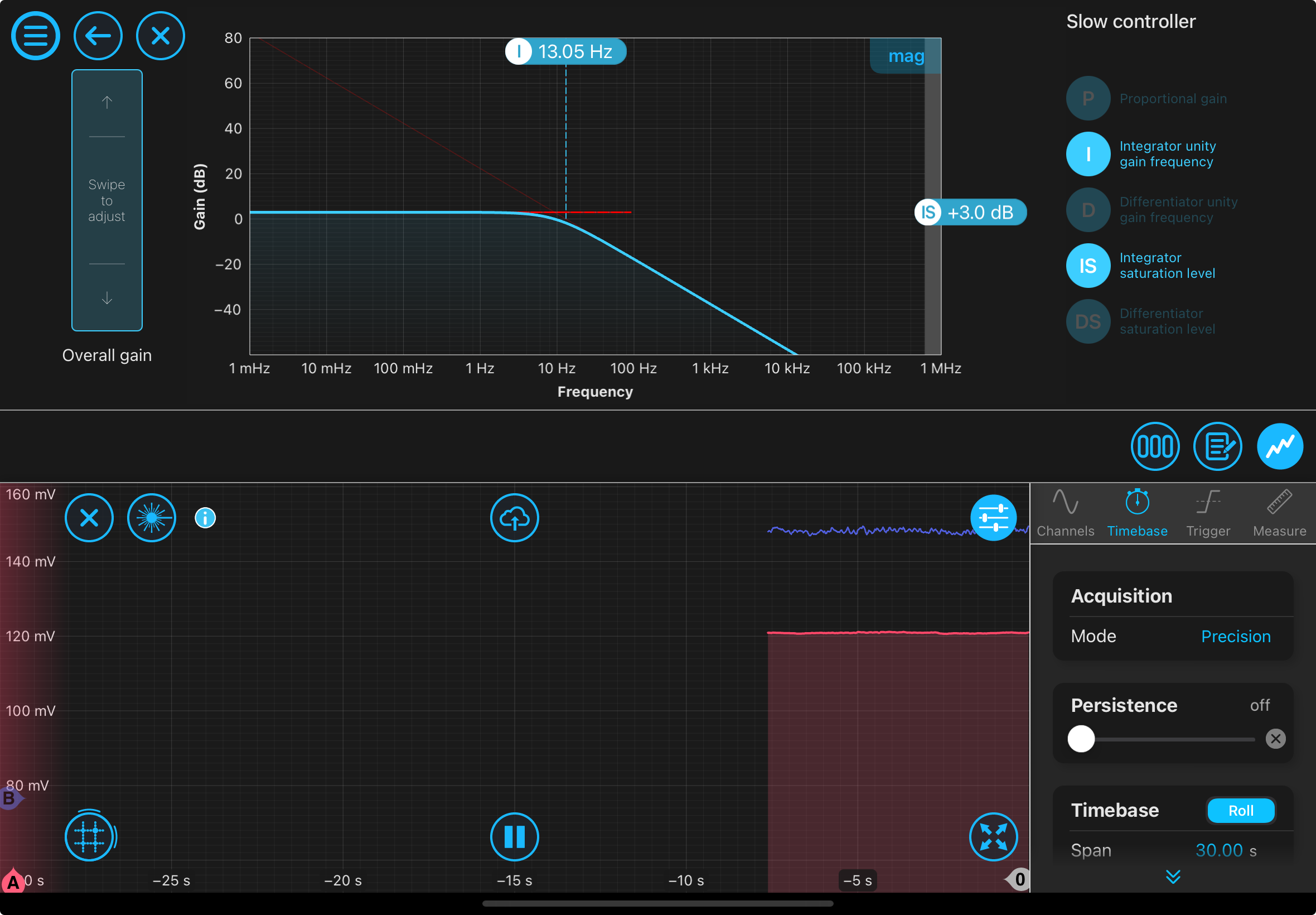
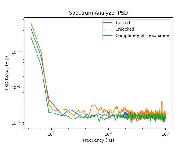
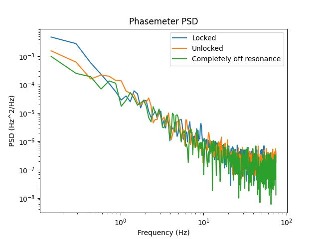
I took data for locked/not locked with a ~3 Hz integrator unity gain frequency and low ~2 dB integrator saturation level (data in NextCloud Users/briana/8_10_2024/noise spectrum probe test). The phasemeter and spectrum analyzer PSD disagree in which situation has the highest noise, although they are in different units. I have not found how the phasemeter converts to Hz/sqrt(Hz), so this could be a reason for the diagreement. Also, I am now again doubtful of the expected order of magnitude of the frequency noise spectrum after looking at the phasemeter ASD.
Should we use the phasemeter? According to Liquid Instruments, the phasemeter measures frequencies around some acquisition frequency and uses a feedback loop to determine the phase of the input. The signal passes through a mixer and lowpass filter but the signal is mixed with some oscillator. This feedback loop tries to minimize the difference between the input and output frequency, which allows it to determine the frequency/phase. Another oscillator allows it to measure the amplitude. The phasemeter operates on a phase-locked loop, meaning you try to keep the phase of the output constant compared to the phase of the input. Because of this, you need to ensure a phase lock can occur (steady input signal needed), which is more difficult at low frequencies. So, this may not be the optimal instrument for measuring this signal since it relies on a lock and our signal only is affected at low frequencies.
I am going to do a more systematic test of the controller parameters (different gains, unity gain frequencies). I was previously just playing around with values but not documenting the controller well. I will also start taking unlocked laser noise spectra far from resonance to see if the way I'm taking data is causing this phenomenon.
Potential reasons for why locked noise spectrum has more noise?
-
Controller issue (feedback gain is too high). I wonder if the shifting polarization of the laser is an issue because that introduces intensity noise, which may start dominating even more with the feedback.
-
As Torrey pointed out, it could be that there is more noise with the lock because of shot noise (at the absorption dip, you have less photons so shot noise should increase).
-
Asymmetry of the error signal shouldn't matter because we just care about the linear region. Can the offset of the error signal from zero be an issue? Changing the modulation frequency (not phase shift) shifts the error signal up to avoid offset at the cost of error signal maximization.
-
Is it possible for the zero-crossing point to shift? Ian suggested that if the zero crossing point shifts, the frequency discrimination might be lower, especially if the zero crossing point reaches the ends of the linear region. The system is now not sensitive (the error signal is smaller for larger frequency deviation) so it is less good at reducing noise.
-
Mode hopping of laser. Probably not because this would cause sharp changes in the locking/photodetector signal, which is not apparent in our data (article by rp-photonics.com).
Other
From Thorlabs specs, the EOM should actually be operating between DC and 100 MHz. Somehow, operating at 120 Hz gave the most symmetric and maximized error signal (400 microvolts amplitude), but it is clearly not built to operate at this level. Anyways, the maximized error signal is now at an EOM driving frequency of 48 MHz (200 microvolts in the positive y direction, 150 in the negative y direction).