[Briana, Ian]
Wiggles in probe scan:
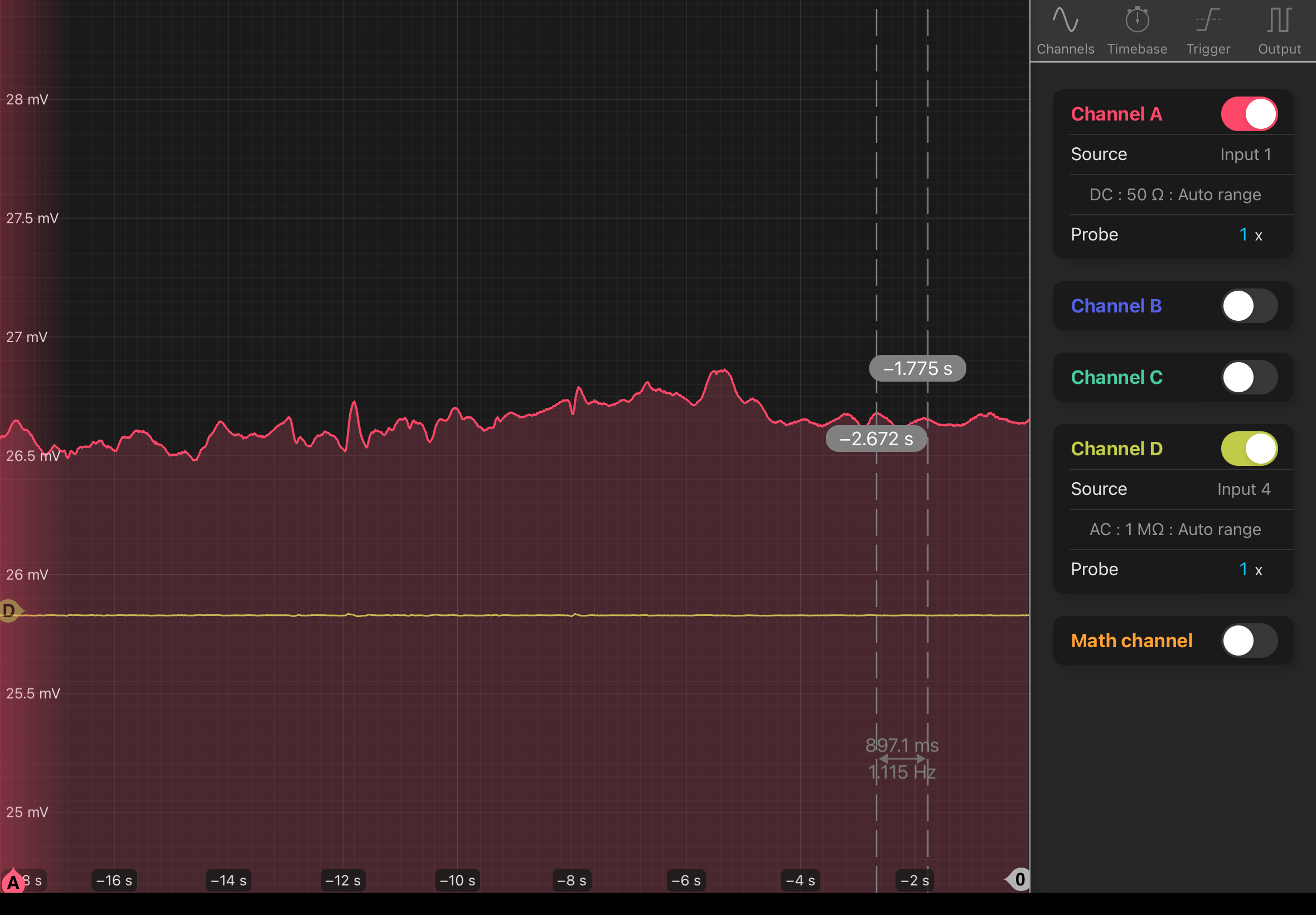
The wiggles tend to be about 0.4 mV in amplitude and a frequency of 4.6 Hz, as seen here. When we are not applying any modulation frequency or temperature scan, we see some variation in power because of the issue with the polarization-maintaining fiber, as seen here. On shorter timescales (zoom in a bunch), there is an additional ~60Hz oscillation, which is apparent whether you're scanning temperature or not. I think the wiggles have been there all along but were just less obvious when I zoomed into the main peak or zoomed out on the power scale.
My best guess right now is that the power fluctuations are interfering with the scan features in the scanning signal.
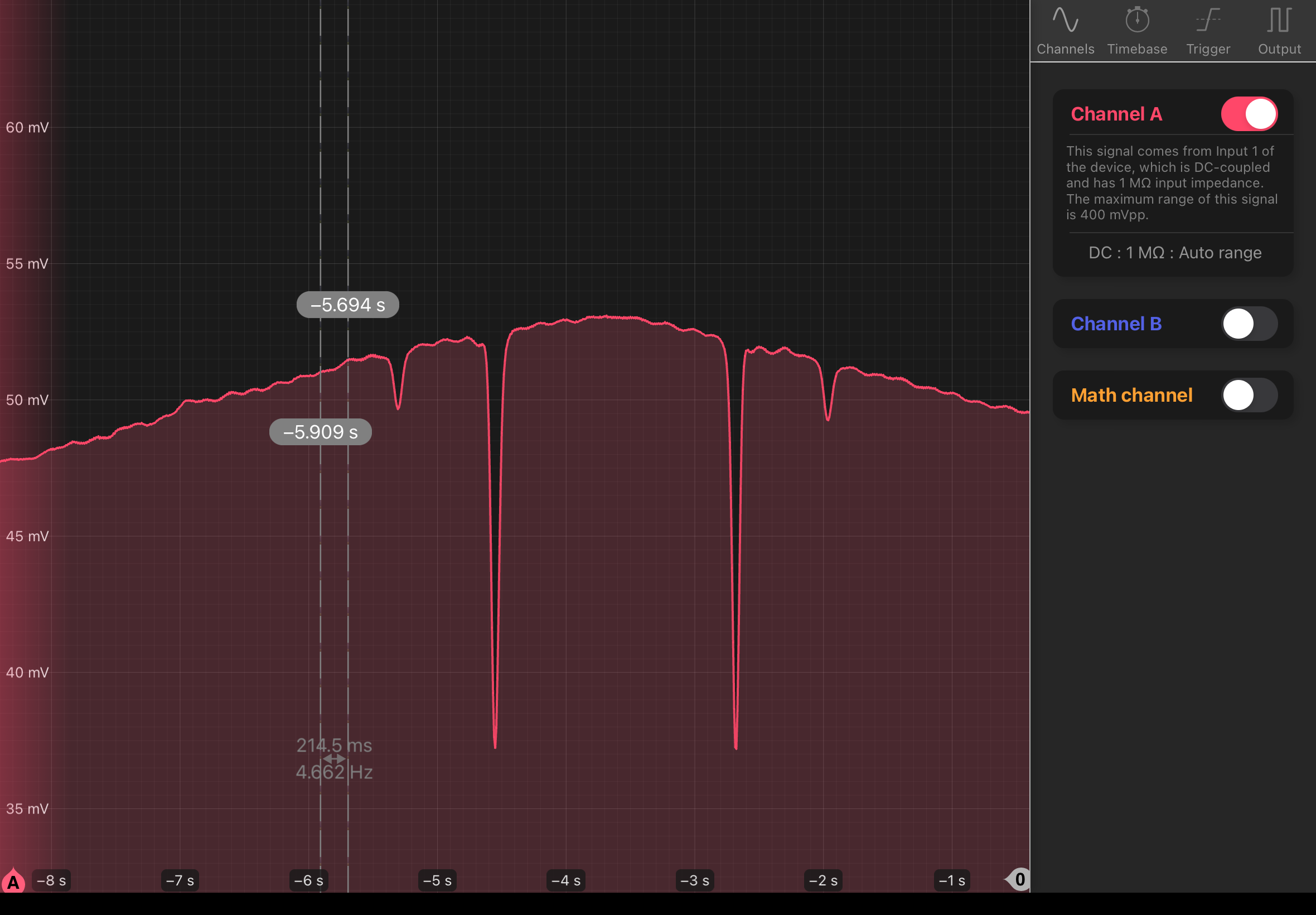
Things that don't affect the squiggles: decreasing the current, moving the fiber, scanning manually. Changing the scan frequency by a factor of two also decreases the frequency of this wiggle by approxiately a factor of 2 as well. Amplitude remains relatively unchanged. mod_200_20240812_174825_Screenshot.png
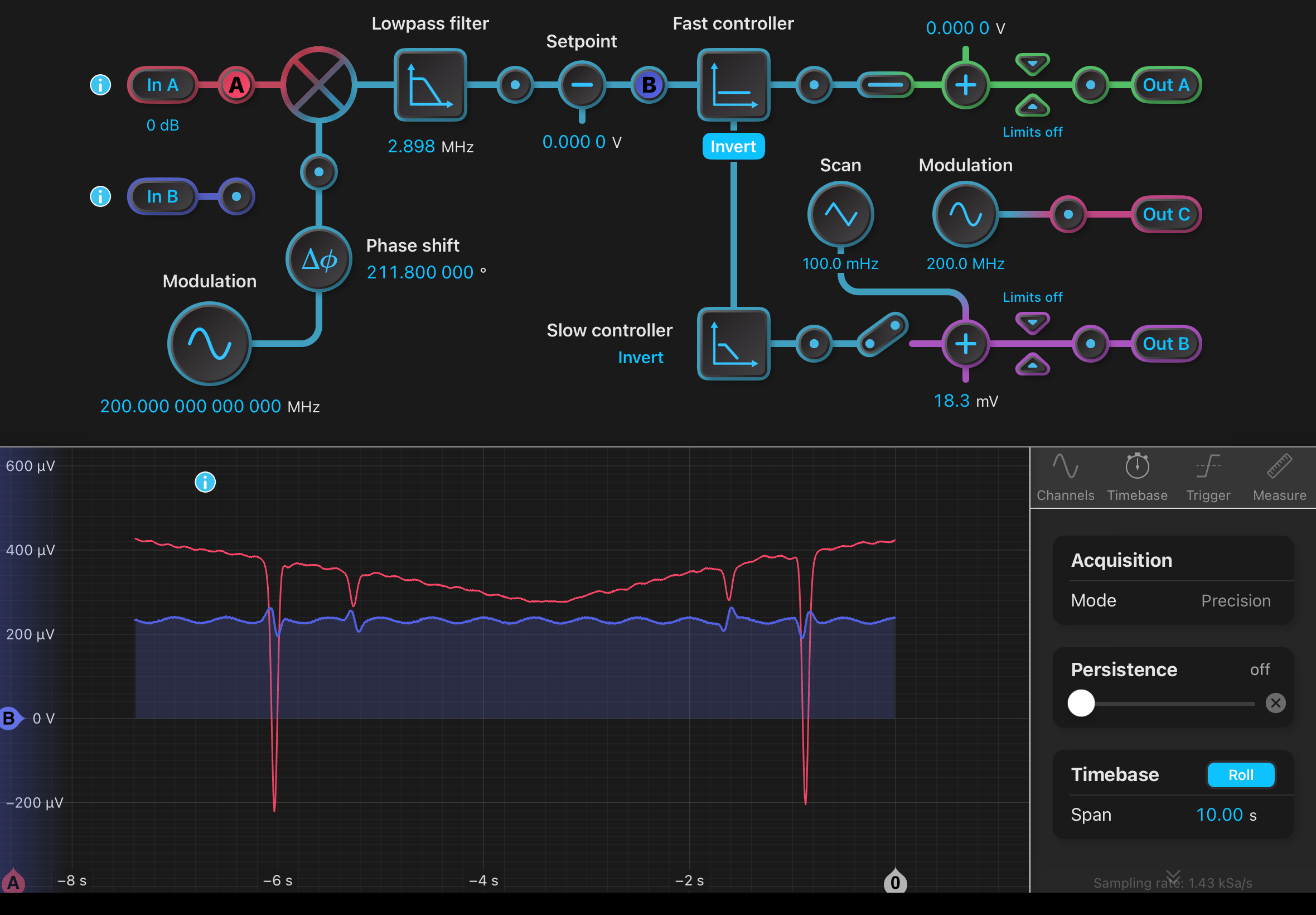
However, by tuning the modulation frequency/phase, you can suppress some of the oscillations in the error signal and also reach zero offset. If you choose a high modulation frequency, as seen here, the wiggles become much more obvious in the error signal. Based on my zooming, the wiggles' effect on the actual asymmetric error signal don't seem to be that significant, although it's still not ideal for them to exist.
Why is the error signal offset?
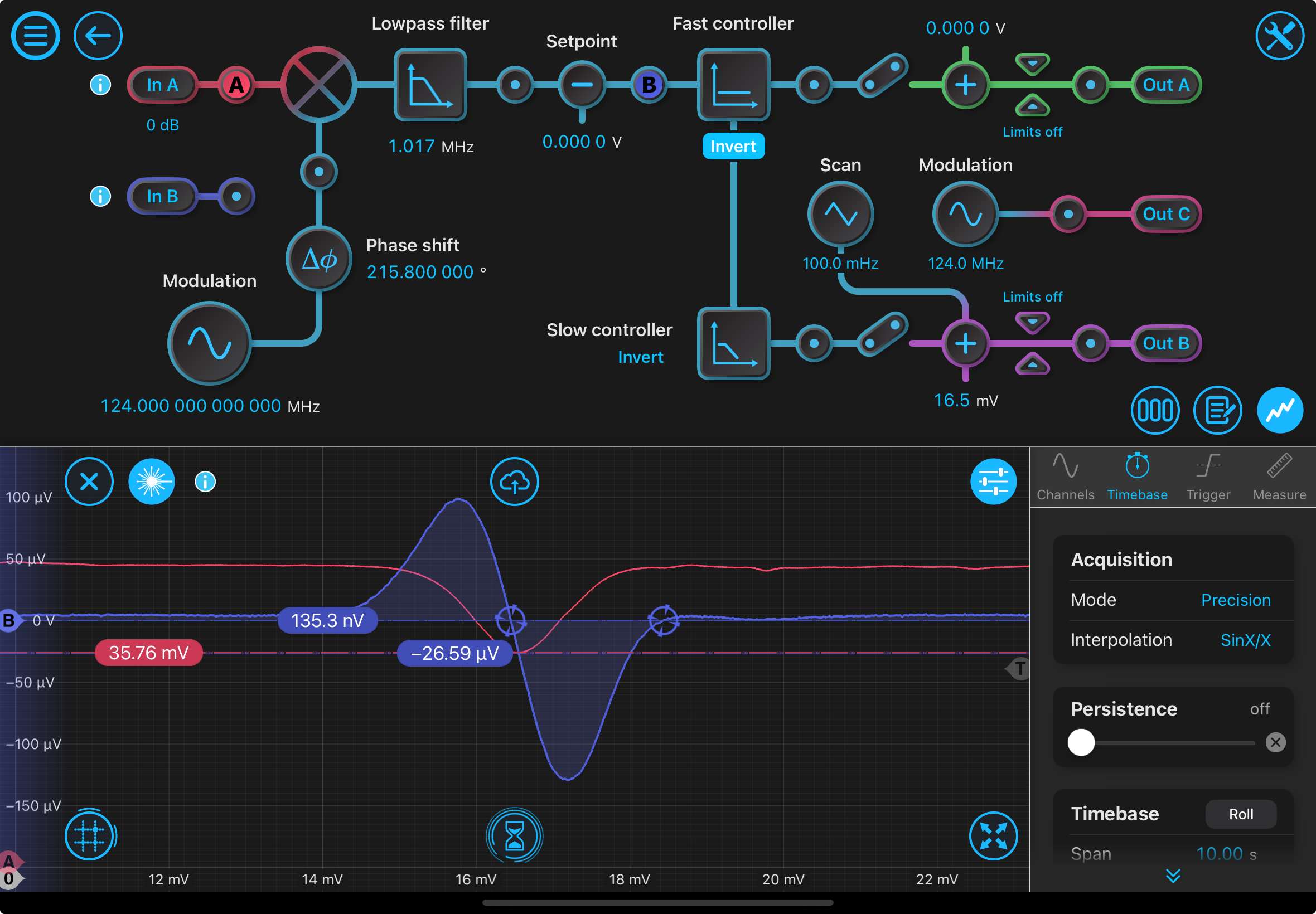
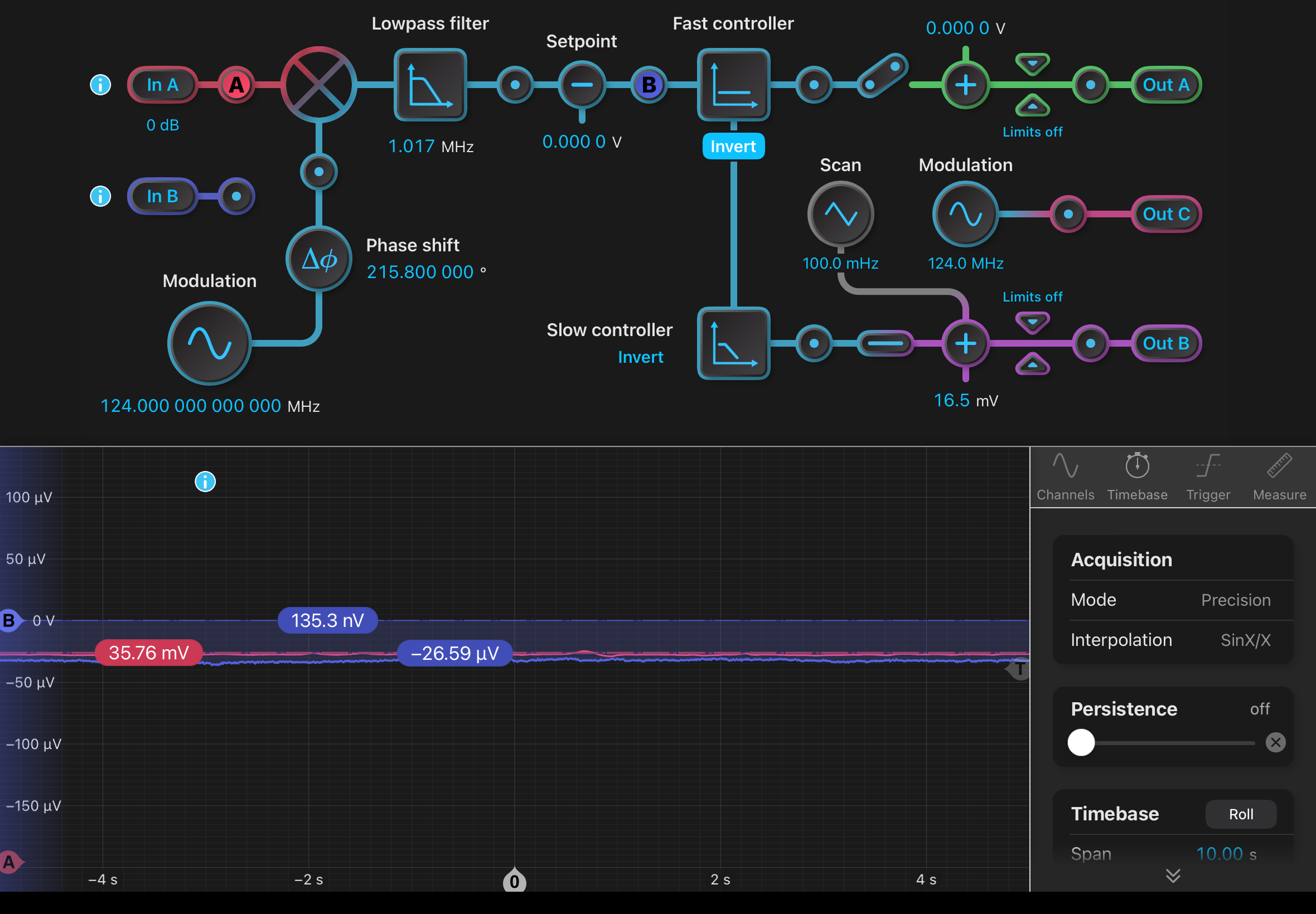
The error signal, when locked, is not at 0 Volts, it is some offset away as seen in this image (purple is error signal, red is photodetector): offsetafterlock_20240812_182448_Screenshot.png. I think what's going on is because the zero-crossing point is offset from the minimum of the peak, the systems locks (see errorsignaloffset.png) to where the error signal intersects the absorption dip minimum. At error signal = 0, the temperature is detuned from the absorption, so the error signal needs to be at an offset.
Other:
Optimized PID controls of the vapor cell, which you can do automatically by going into Menu -> Ch 1 PID controller -> Auto-tune. Now, the temperature varies at most by 0.05 Celsius in comparison to the 0.5 Celsius oscillations before. This did not fix the wiggles.
I locked with just the probe at an integrator unity gain frequency of 7.029 Hz and an integrator saturation level of 6.0 dB. After being enlightened about the matplotlib PSD function, this may be the ideal way to get the power spectrum since the Moku is limited at lower frequencies. We took data with a sample acquitsition frequency of 5 kSa/sec for 20 seconds when the laser was locked and not locked. Then, we get the PSD with the following parameters which follows a good averaging method (Welch method): detrend = linear to remove any linear shape in the segments of the power spectrum, Hanning window which is most widely used for making the signal as periodic as possible, NFFT = 256 for standard number of frequency points in the FFT.
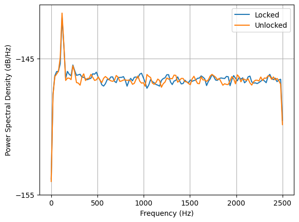
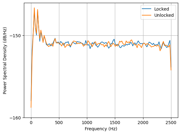
Lee suggested bit noise from the Moku may explain the previous noise spectra. We want to minimize quantization steps in the digitization process (converting the voltage reading to a digital value), so to do this we want to increase the analog signal as much as possible. Increasing the gain on the signal would accomplish this even though the gain amplifies other signal noise. I have not figure out how to increase the gain of the error signal because it might not be possible to increase the gain at a probe point in the laser lock box in the Moku. You could add in the lock-in amplifier but it's a hassle for tuning parameters. Amplifying just the input signal has not proven successful for increasing the error signal. For now, I've taken data with DC at different impedances, which should give an "estimate" for the different gains. The PSDs are shown here: 50_Ohm_impedance_comparison.png, 1_MOhm_impedance_comparison.png. At a higher "gain" (in this case, 1 MOhm impedance means the divider effect is closer to 1 compared to the 50 Ohm impedence which would divide out the signal by some factor less than 1), we would expect more noise so this matches well with the 1 MOhm vs. 50 Ohm PSD comparison. There seems to be no distinction between the locked and unlocked case at either impedance and artifacts in the 50 Ohm one that are not present in the 1 MOhm, not sure why but will retake data tomorrow to make sure it was not some silly mistake.