[Jeff, Torrey]
We had some plans for filter cavity diagnostics to be done, first step in accomplishing this is locking a filter cavity with an AOM. This has been done. This post will describe the process in case anyone wants to replicate this in the future.
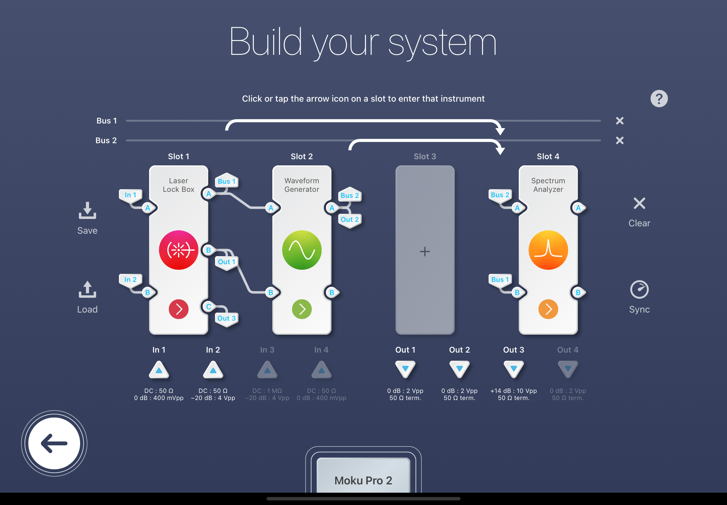
Attached is a screenshot showing the multi instrument mode used to accomplish this. Inputs and outputs are as follows:
Input 1 - Cavity REFL PD
Input 2 - Cavity TRANS PD
Out 1 - To the DC modulation port of the laser
Out 2 - RF in of AOM
Out 3 - RF to EOM to create sidebands
The idea is very similar as in previous posts. Create sidebands on EOM, demod in laser lock box to give an error signal, fast controller output goes to Waveform Generator which acts as a VCO (accomplished by choosing frequency modulation and input A as the reference voltage). And thats it! Relatively easy once we had the proper loop in mind. The output on the slow controller is to the laser (UGF ~10 Hz) to control any low frequency laser drifting which is known to occur. One other note that is worth mentioning is the value for the frequency modulation depth needs to be manually set. Since the FSR of the cavity is 125 MHz we initially set this range to be +/- 50 MHz to have enough range. You could also set this lower, to say 5 MHz, and then scan around on the laser to find the resonance in this range.