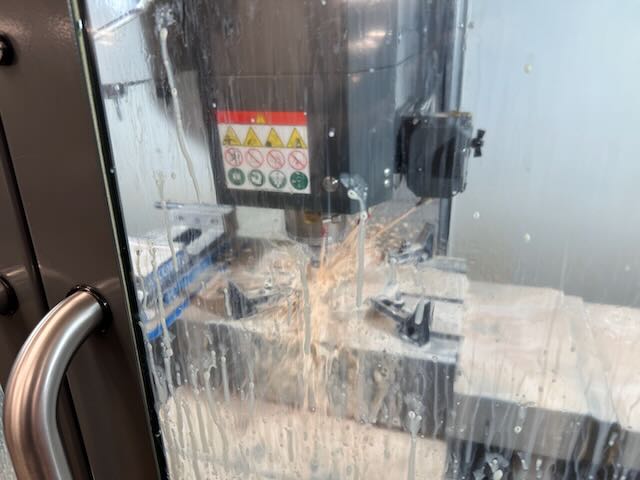
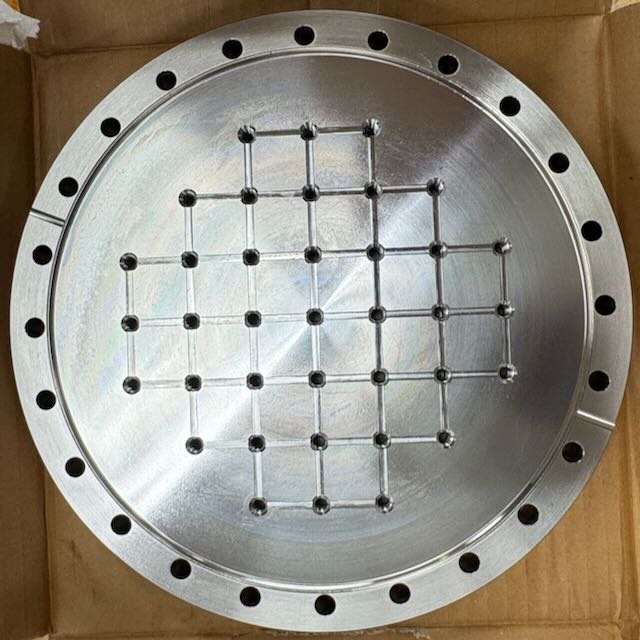
I ran the attached CNC code on the Haas VF-2 to add 37 tapped 1/4-20 holes with 1" spacing (a breadboard hole pattern) to a 10" CF Flange. I added a 0.0156" deep groove for venting so that we can cover a hole and not have a virtual leak.
The "pipeline" was to design the part in SolidWorks (CAD), give some CAM commands (tell it what holes to drill, how deep, etc), then "post" the G Code. I then copy the G Code into .txt file adn import it into the python script. This python script adds a custom cycle call (M97) to remove chips and allow me to visually confirm this. I then copy the code's output into a new .nc file. I then add the custom cycles at the bottom of the code. I can then read this G Code in the Haas.
I attached the flange the same as this post. Because the part and tool are flooded with coolant, the masking tape didn't do a great job at holding the flange to the knife edge and some chips got under the copper gasket. Luckily, these chips did not scratch the knife edge. I think the flange helped.
I used the 4 following tools: this #4 Cobalt Steel drill bit with a TiN coating, a 3/8" diameter 90° chamfer tool, this 1/4-20 steel bottom tap with 3 flutes and a black oxide coating, and a 1/8" diameter carbide end mill with 4 flutes and a TiAlN coating.
The tools did not appear to be too worn out after this cycle. There is a bit of wear on the tap and end mill, possibly due to earlier use.
After machining, I carefully removed the chips and used a stone and WD 40 to remove burrs from end mill.
I am going to machine another flange tomorrow and clean these Friday so that they can be baked out over the weekend.


This should probably be in the "Vacuum Systems" section not "GQuEST General"
This should probably be in the "Vacuum Systems" section not "GQuEST General"