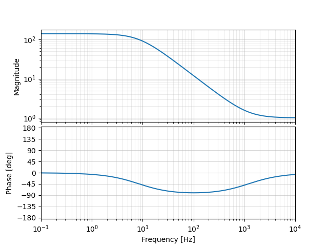
Here is an example of a stabilizing controller we have used to lock the cavity, described in a few ways.
In the Moku UI it is described as:
Fast controller: PI controller: proportional gain +0.0 dB, integrator crossover 1.2 kHz, integrator saturation +43 dB, invert on
As a continous time transfer function, described in zpk (zeros, poles, gain) form, this is
z = [-1200*2*pi]
p = [-8.495*2*pi]
k = 1.0
Attached is a plot of the transfer function.
What is the sampling frequency?
Moku is a bit secretive about the details of their digital filter implementation. The PID controllers in the Moku are designed in continuous time but must be implemented in discrete time. At an in-person meeting I asked a Moku technical rep. this question: How do you digitally implement the PID controllers on the Moku? And the Moku technical rep. refused to answer, citing the need to protect industry secrets. We can make some educated guesses using the specs.
• Integrator crossover frequency: 3.125 Hz to 312.5 kHz
• Differentiator crossover frequency: 31.25 Hz to 31.25 MHz
The DAC sample rate is 1.25 GSa/s at the output of the Moku, but as far as I understand this can be decoupled from the clock rate of the digital filter by using downsampling or interpolation.
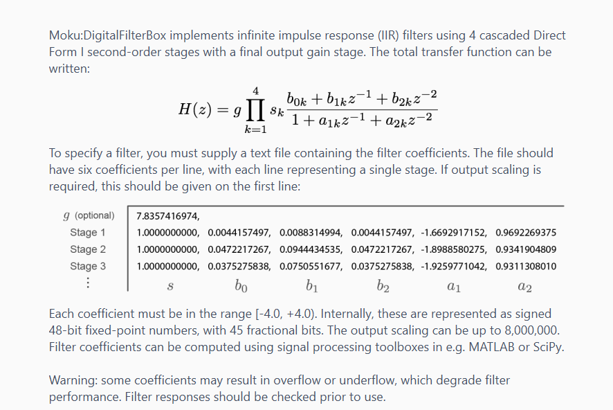
Moku does give more information about their "Digital Filter Box" which is a more general IIR filter compared to the specific PID controller. Their IIR filters have a sample rate of 39.063 MHz and they use "48-bit fixed-point numbers, with 45 fractional bits." Attached is a screenshot from the user interface that explains a bit about their IIR filters.