Continuation of 12055.
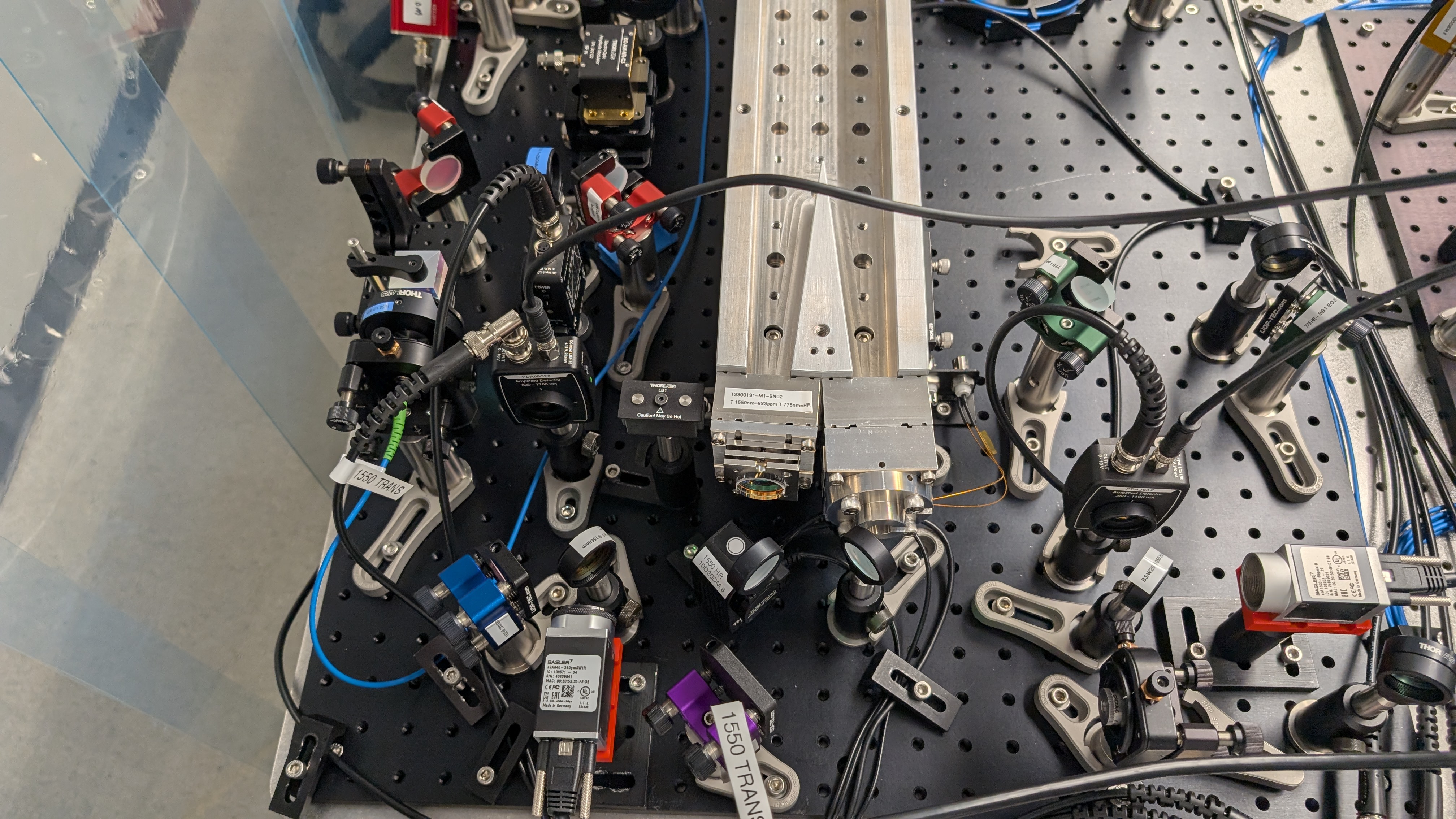
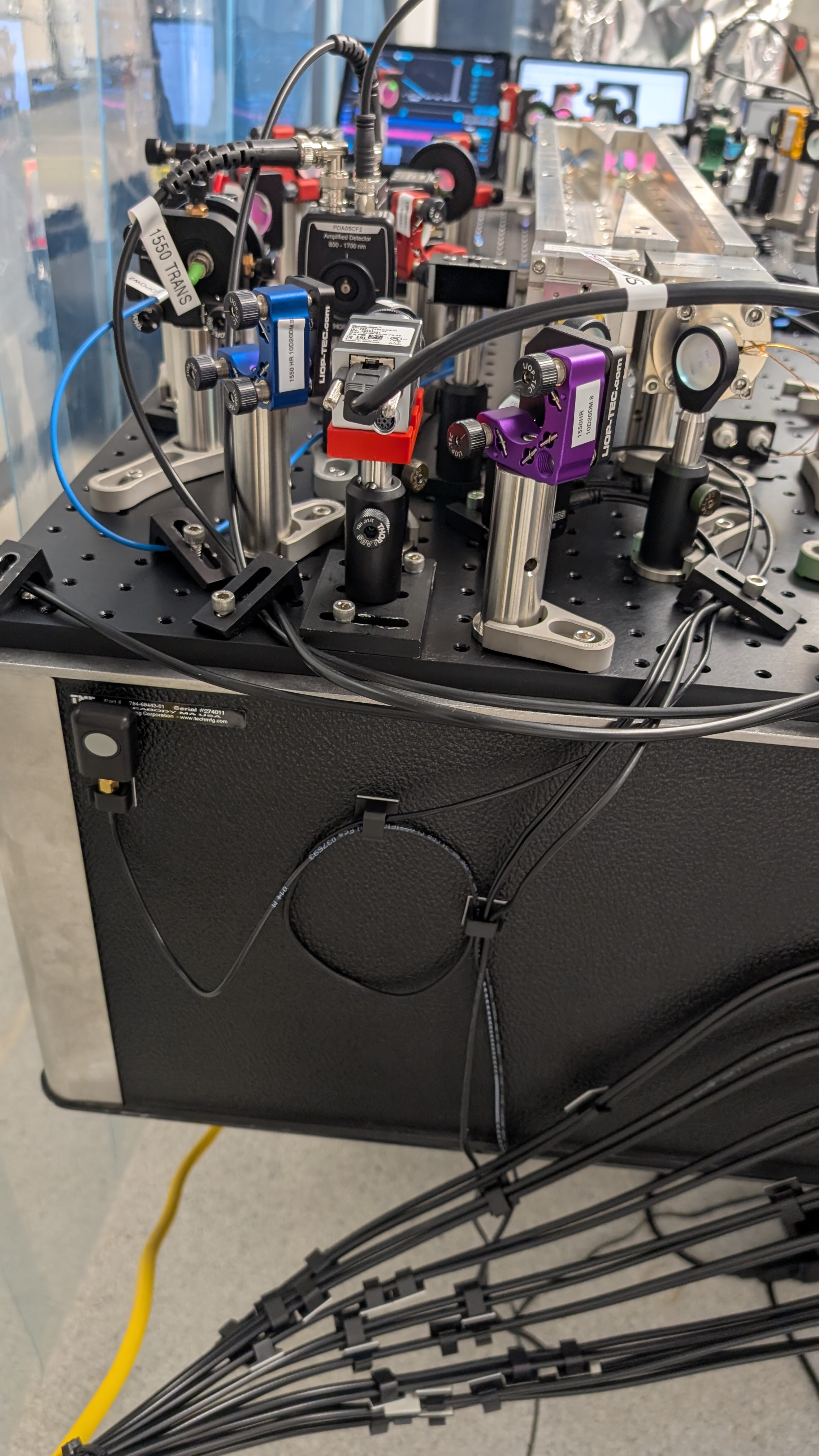
I touched up the alignment of OFC1 1550 path until it looked good enough to lock. I locked the cavity with the laser in order to see a constant stream at the output. I then used this to align all of the transmission optics outlined in the previous post. This works great and everything is aligned. Here is an overhead shot of everything in action. Note the three cables coming from the flipper mirror. One is power, one is a physical button located on the side of the table that can be used to flip between the transmitted light on a camera/PD combo or chaining to the next cavity, and the third is a USB that can be hooked up to the computer but is not currently because i can't find a USB extension (this will also be cool because when we make guardians to control the cavities these can interface with python I believe). I really like this design where we can quickly flip between diagnostics and cavity chaining modes. Other minor note is the flip up mirror path being the diagnostic over the connection to the fiber should prevent us from having to make minor adjustments into the fiber when changing modes, but this MAY be required if the repeatability of the flip up mirror isn't good enough to center on the PD/camera each time. After clicking the button 15 ish times it seems like its more than enough, just something to watch for.
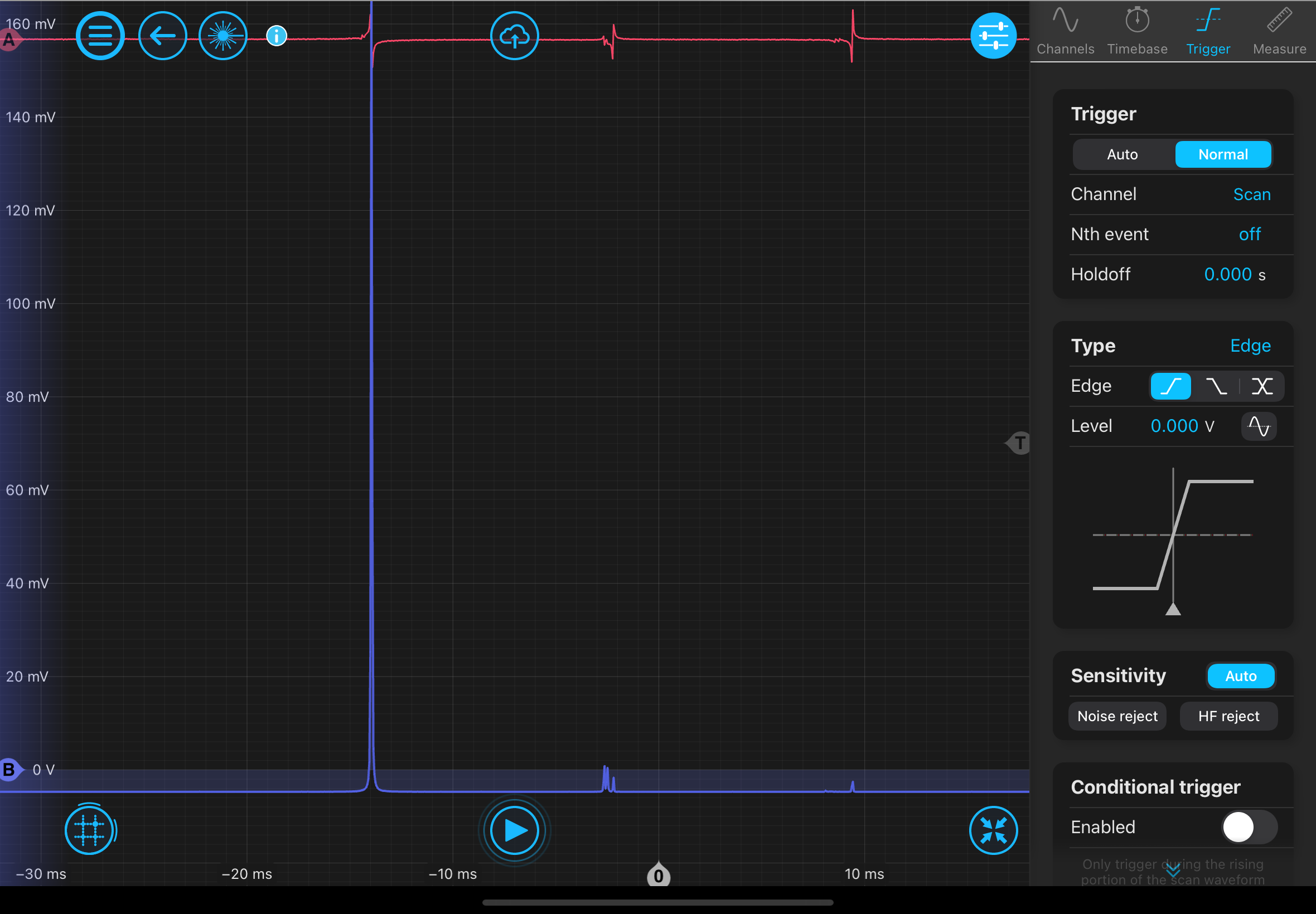
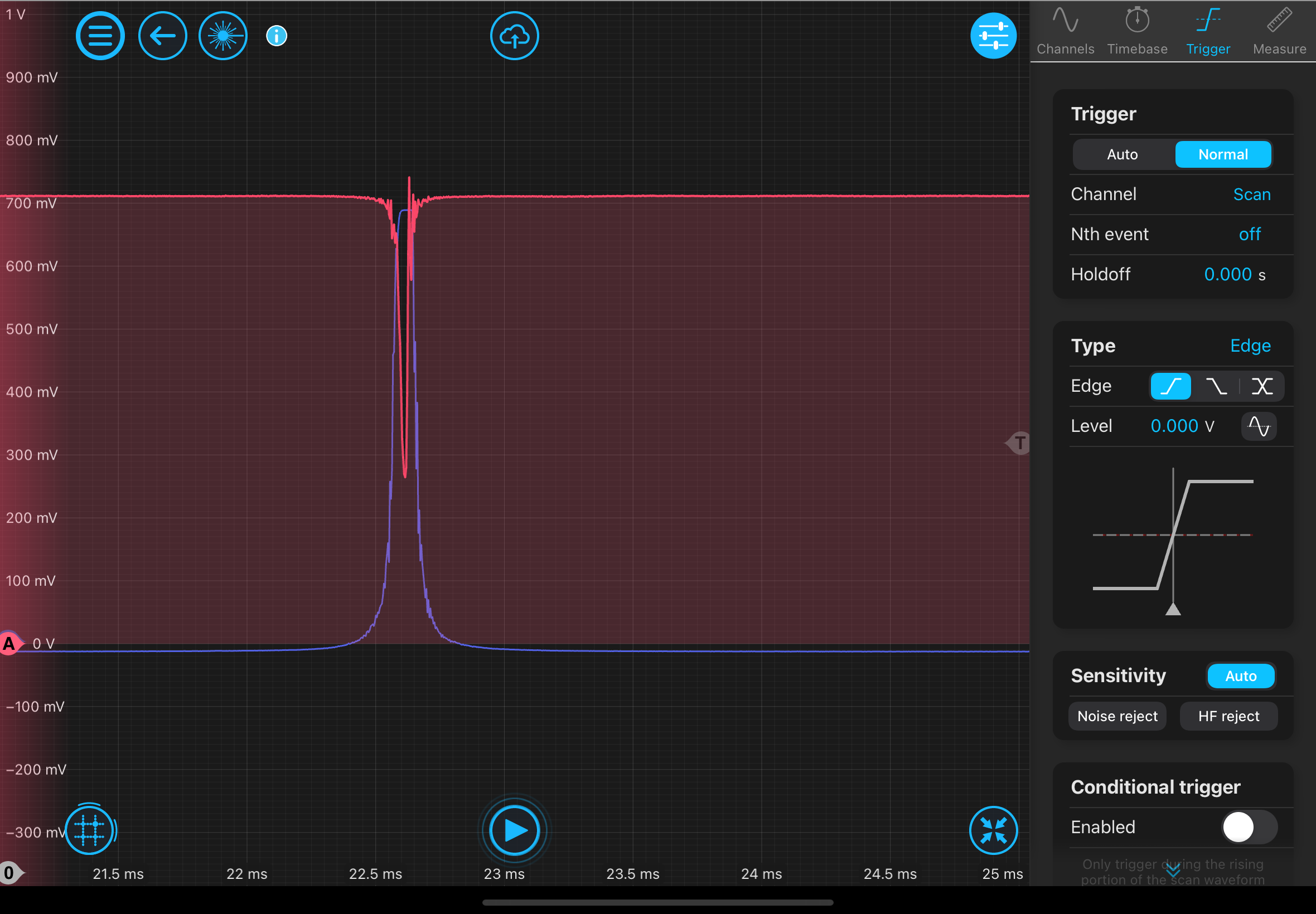
Saved some screenshots of some quick cavity scans. This is showing the REFL and TRANS bd of the 0,0 mode. Note that it does not look like the cavity is close to critically coupled (we have never seen this cavity critically coupled even in B102). And then this shows the difference in the 0,0 mode and the rest of the higher order modes leaking through. This may be able to be improved via finer alignment and adjusting mode matching but is more than enough for the science we want to do now.
I think I want to retake some ringdown measurements to see how dirty the cavities became after the move and align the output into the fiber that connects to OFC2. Pending this and a quality piezo lock on both cavities we are ready for a carrier suppression measurement of both cavities.
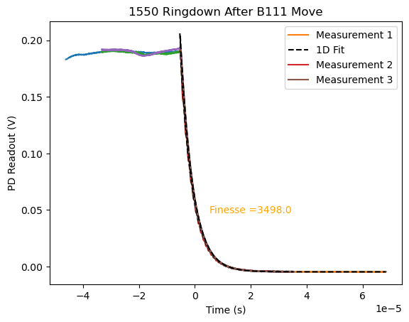
With things realigned, did a quick check that we didn't dirty the mirrors in OFC1. OFC1finesseaftermove.png results from breaking a 1550 lock in 3 different ways (data is at "\Nextcloud\GQuEST\Measurement Data\OFC1 Finesse\" ). Finesse seems good, if not slightly higher than before.
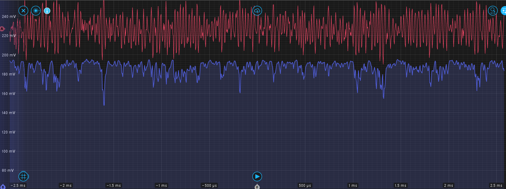
Other couple of notes via screen shots: this shows the transmitted signal in blue. This is a good visual interpretation for how good the laser lock is currently. Losing lock and regaining on the 50 us scale. The max lock loss is roughly 1/4 the total transmission.
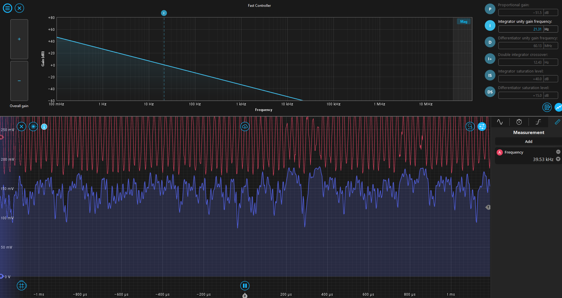
This one shows that the UGF for this loop is much lower now that the LNA is in front of the laser control. There should be a factor of 10. Also moving the UGF above 20 Hz rings something up at around 40 kHz. I believe this is new.