[Jeff, Sander, Alex, Daniel]
I cleaned the inside of the 5" long, 10" to 8" nipple. We then slid the input vacuum cube on Laser Filter Cavity (LFC) toward the 5 in Long 8 in CF flange bellows. We stuck screws through the nipple and eventually through the bellows as well, getting them somewhat tight with plate nuts. We then further slid the input vacuum cube into place and bolted it down. Jeff and I then removed the screws on the top half of the connection and loosened the others so that we can drop in the copper gasket. The gasket was not properly seated intially, so Jeff pushed the gasket up and away and the gasket dropped into place. We reattached the screws and tightened all the screws. I still need to tighten the screws to ~23 Nm. Waiting a bit for the bellows to plastically deform back might make this easier.
I thought we would want to use the engine hoist, but we decided to just push the cube. We did make some metal to metal contact, but I think the knife edge is ok. I briefly inspected the window attached to the output cube since it is fragile, and it looked fine. I have no real reason to expect damage. I'll install the input window last.
I measured the length from the center to center of the vacuum cubes (around where the mirrors will go), and it is 44 in (1.12 in), almost exactly what Ian designed.
See attached photo.
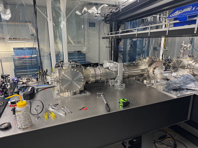
I tightened the connection to 20 Nm. There is a stainless to stainless connection around ~90% of the flange surface.