We have one working clock circuit for a cymac main chassis. We have two more PCBs which are both slightly incomplete.
Today I went to Downs and Todd flashed our 3 arduino nanos with the software outlined in LIGO-E2300449. The steps look simple enough, but since Todd had already done this for his Arduinos it was as simple as connecting to his computer and hitting upload.
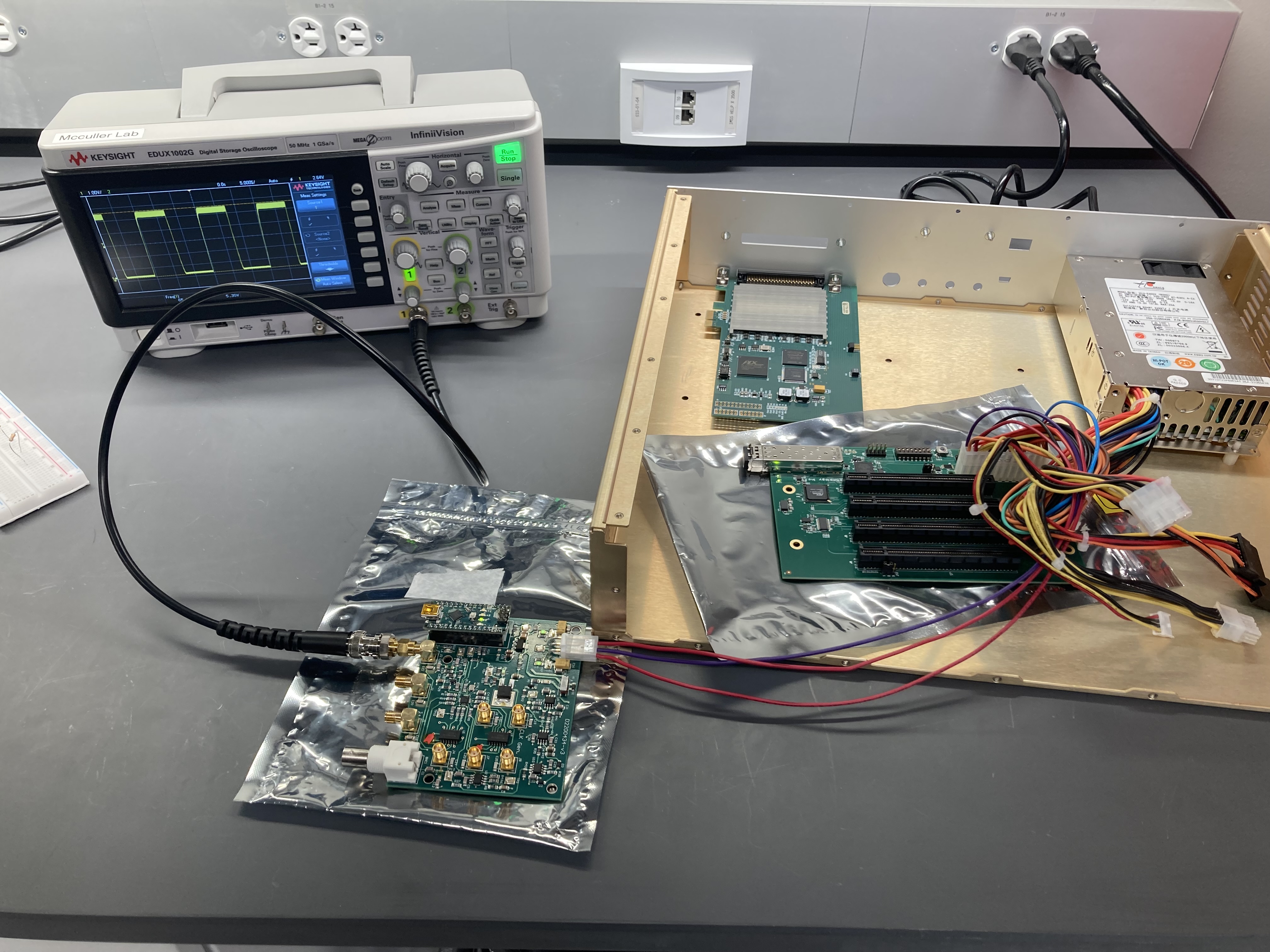
I then returned to bridge where I tested one of our clock circuits. I learned that the ATX power supply only outputs a voltage if the large ATX connector is plugged in, hence the PCIe backplane resting on the anti-static bag in the photo.
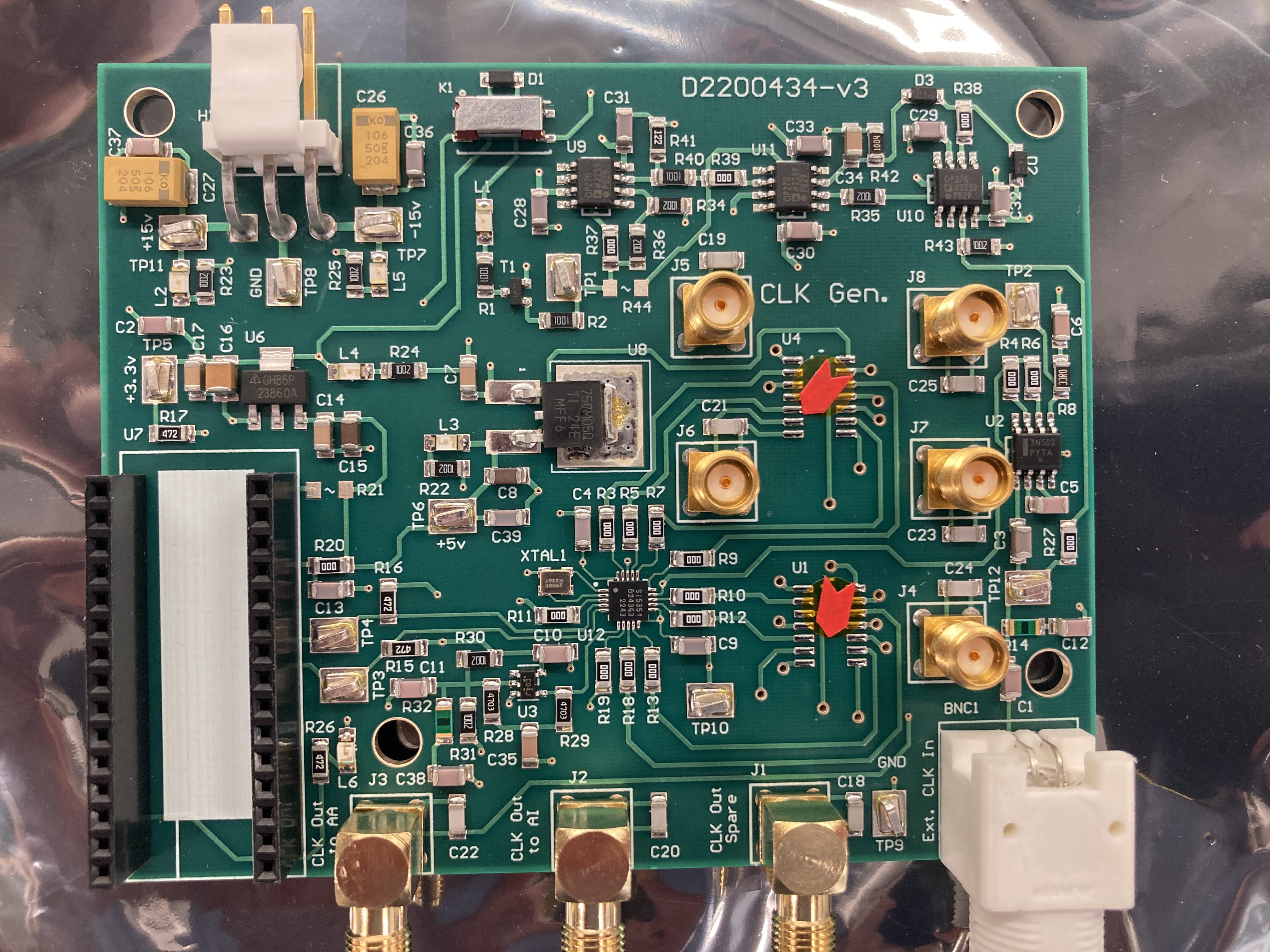
The one complete clock PCB that we have works. We have two more PCBs from Todd, but they are each missing a component or two. One is missing two buffers (center and marked by orange) and the other is missing an RF relay (look top, K1) Perhaps I will work with Todd to complete them.
It is also possible that we don't need the relay, which appears from the schematic to be related to the external input.
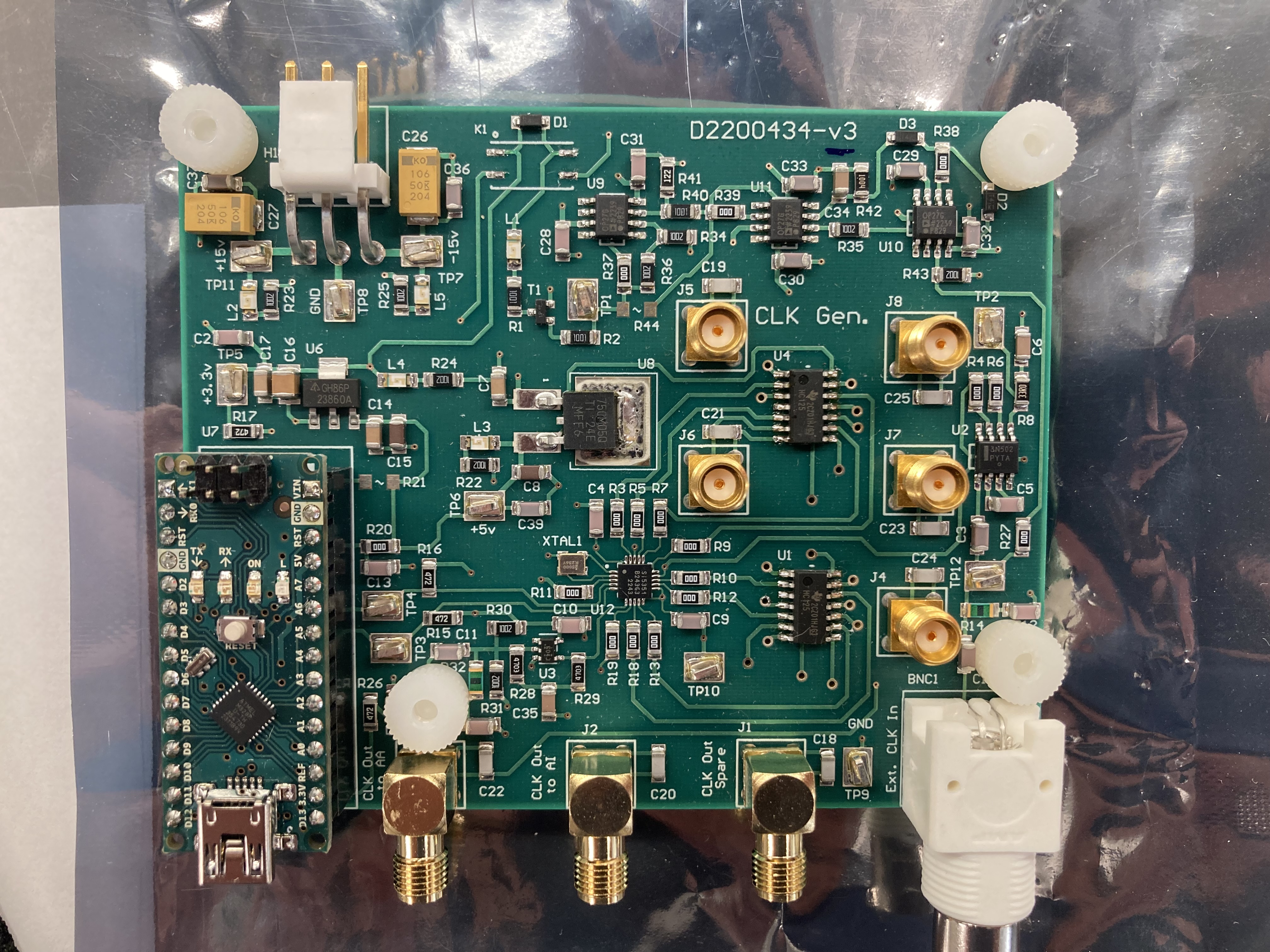
The clock circuit which is missing an RF switch (component K1) produces three 65kHz outputs above 5 volts. The external clock input has not been tested.