[Alex, Daniel]
A bushing for a Newport 100 thread per inch (tpi) AJS screw is made of brass and therefore cannot be used to hold (and be held by) stainless steel because it thermally contracts when the dewer cools down (this part will be around 40 K). This has been experimentally seen by Alex. Instead of brass, Alex and I think we should use a 304 stainless steel or copper 101. The advantage to using stainless steel for the bushing is the identical thermal contraction to parts around it. Stainless steel 304 is cheap and fairly easy to machine compared to other alloys. The disadvantage of stainless steel is cold/vacuum welding to the surrounding parts, so copper is a good alternative with a nearly identical thermal contraction. Copper contracts 0.322% from room temperature to 40 K compared to stainless steel's 0.296%; brass is 0.380%. Beryllium copper contracts at 0.315% but is much more expensive than (nearly) pure copper, so we chose copper. All data from here, appendix A6.4
To test the fit and the G-Code, I made the bushing out of aluminum, except the threads because we are waiting on the tap. I also used a slightly oversized drill because we are waiting on the correct drill size. Attached are the SolidWorks CAD/CAM file and G-Code file.
The part I made looks good. I tweaked the G-Code from what I ran to what is attached to account for some issues with the cut and changing the material. Changing the material may require me to change the spindle speed, cutter feed rate, and depth of cut.
Alex has also enquired about Thorlabs or Newport making the bushing, but I doubt it would be quick and affordable.
[Alex, Daniel]
I cleaned the bushing and we tested its fit. The bushing does not fit, I think because I calibrated the lathe diameter incorrectly. The diameter to be clamped is 0.381" instead of 0.374". For the real part, I will be sure to check the diameter before the parting operation.
According to Newport, "The AJS100-0.5 uses 303 stainless steel, and the 9066-xy-m-v stage uses 440 and 420 stainless steel." Hopefully this is different enough to prevent cold vacuum welding to out 304 bushing.
After measuring the Thorlabs power supply I wanted to test some of the other supplies we have laying around, to get an idea of what is normal.
I measured the 15V supplies from amazon we previously purchased and found they had about a volt of ripple, at a frequency of 78 kilohertz.
[Everyone]
In order for the drywall to be accessed due to the flooding, we moved equipment out of B111B and B111D into B111A or into the middle of B111B. Some electronics equipment in B111D was moved North and away from the walls. The vacuum equipment in the white cabinets in B111B was moved into the North area of B111A. Much of the other equipment along the walls in B111B was moved into the middle.
[Torrey, Jeff, Daniel]
We moved the Thorlabs ULN15TK and TeraXion Seeder Lasers into the Thorlabs RBX32 19" Electronics Rack. We connected SMA Cables from the lasers to the RBX-SMA. We need another SMA cable (like this), and could use 3 more because the cables we got were a bit long.
We connected the fiber outputs from the seeders to a ADAFCB4 mating sleeve. We need a Fiber 50:50 Beam Splitter on the mating sleeve output and a Faraday Isolator on the TeraXion ouput before the mating sleeve. Torrey purchased both of these.
See attached photo.
We hope to get and install these parts before turning on the lasers after the lab is fixed from the flooding.
We had some trouble shutting the rack. We had to push in some buttons and fins on the rails. The buttons, which probably should be pushed in first, are on the outside. The fins are on the inside of the rails.
[Ian, Jeff, Sander, Georgia]
Summary:
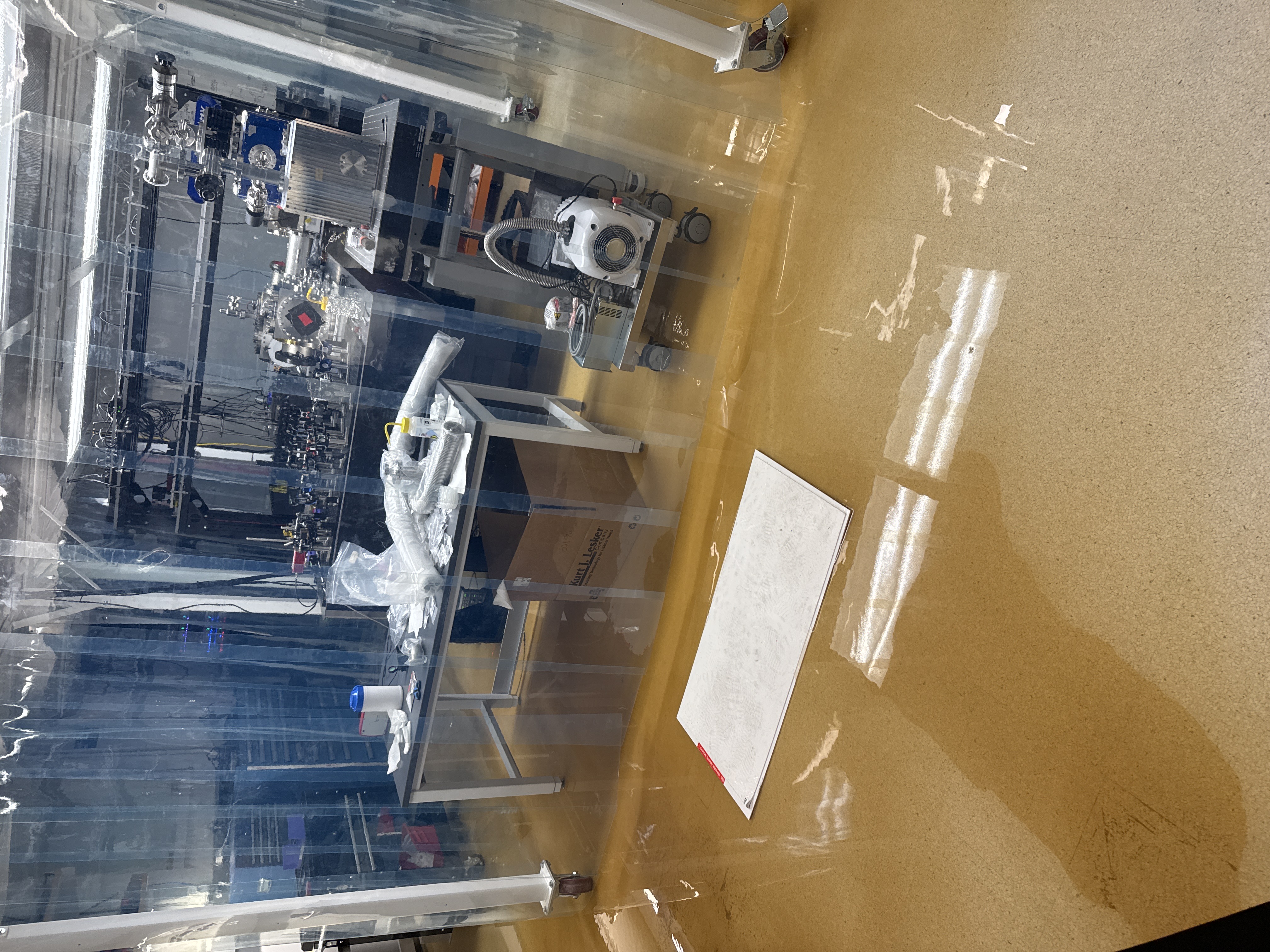
The lab flooded on the night of Feb 6th around 9 pm. There was about 1-2 inches of water in the main GQuEST lab under the optics tables as well as a bunch of fine sediment that came into the lab. We stayed with the facilities staff and custodial staff to clean it up.
Timeline:
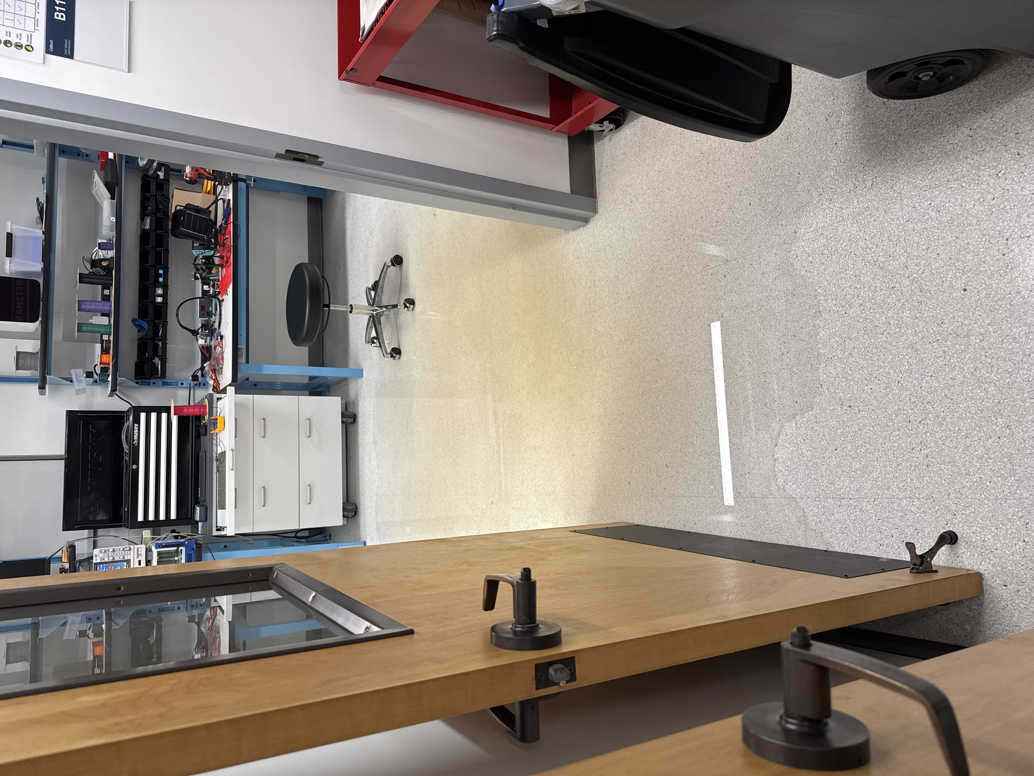
Around 9:50 Jeff came into my office on the second floor of bridge and asked told me the roof of east bridge was leaking. I went with Georgia (Rana's visiting Grad student) and Jeff to check it out. There was water coming from the fourth floor of bridge and going down the stairs all the way to the basement. There was only a little water on the floor in the basement outside our lab so we thought that there wouldn't be water in our lab. We decided to check and found there was about half of an inch of water in the lab (at around 10:15) (First_look_Lab.jpg,First_look_hallway.jpg). Jeff had called Caltech security about the water leak, so we were able to flag down the Caltech security person and facilities staff that had responded to the original flood.
At this point, the water was filling the center of the lab under the optics tables. The center of the room is the lowest of water and sediment was congregating there and the water had started to move out of the main GQuEST lab and into EE shop. At this point, we started to turn off all electronics that could be affected by water that were low. The first thing we did was turn off the laser so that people could enter the room without wearing goggles. The next thing we did was start to unplug all electronics carefully. As water was in the room, electronics were a safety hazard and needed to be turned off carefully. There were a number of power strips on the ground in the water. We were able to turn them off safely and then remove them from the water. We removed all electrical things from the ground, which includes all cables. We turned off all the power to the optics tables, including power from above. We also did this in the EE shop, although there was almost nothing on the ground. We moved the tool chest away from the water.
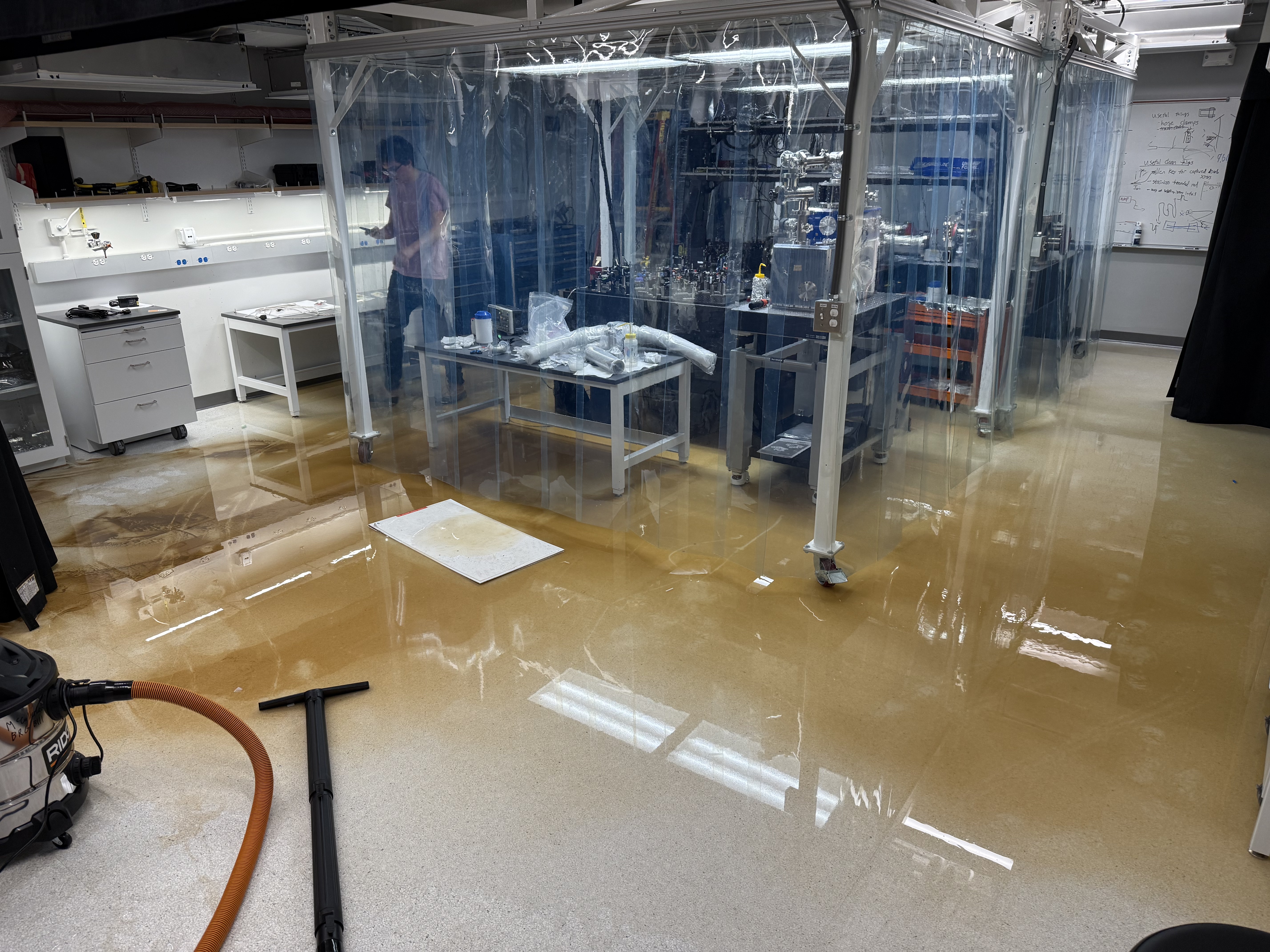
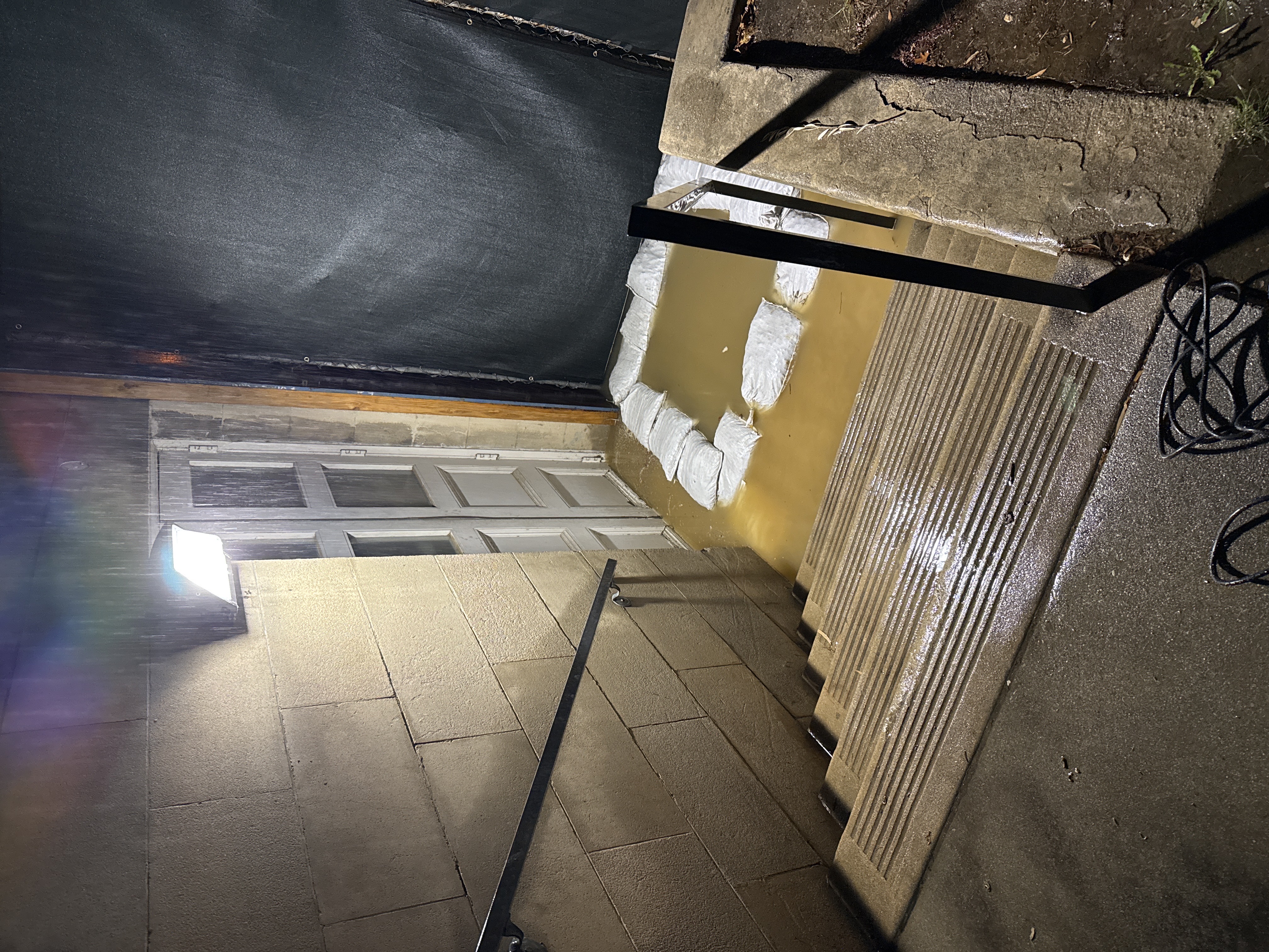
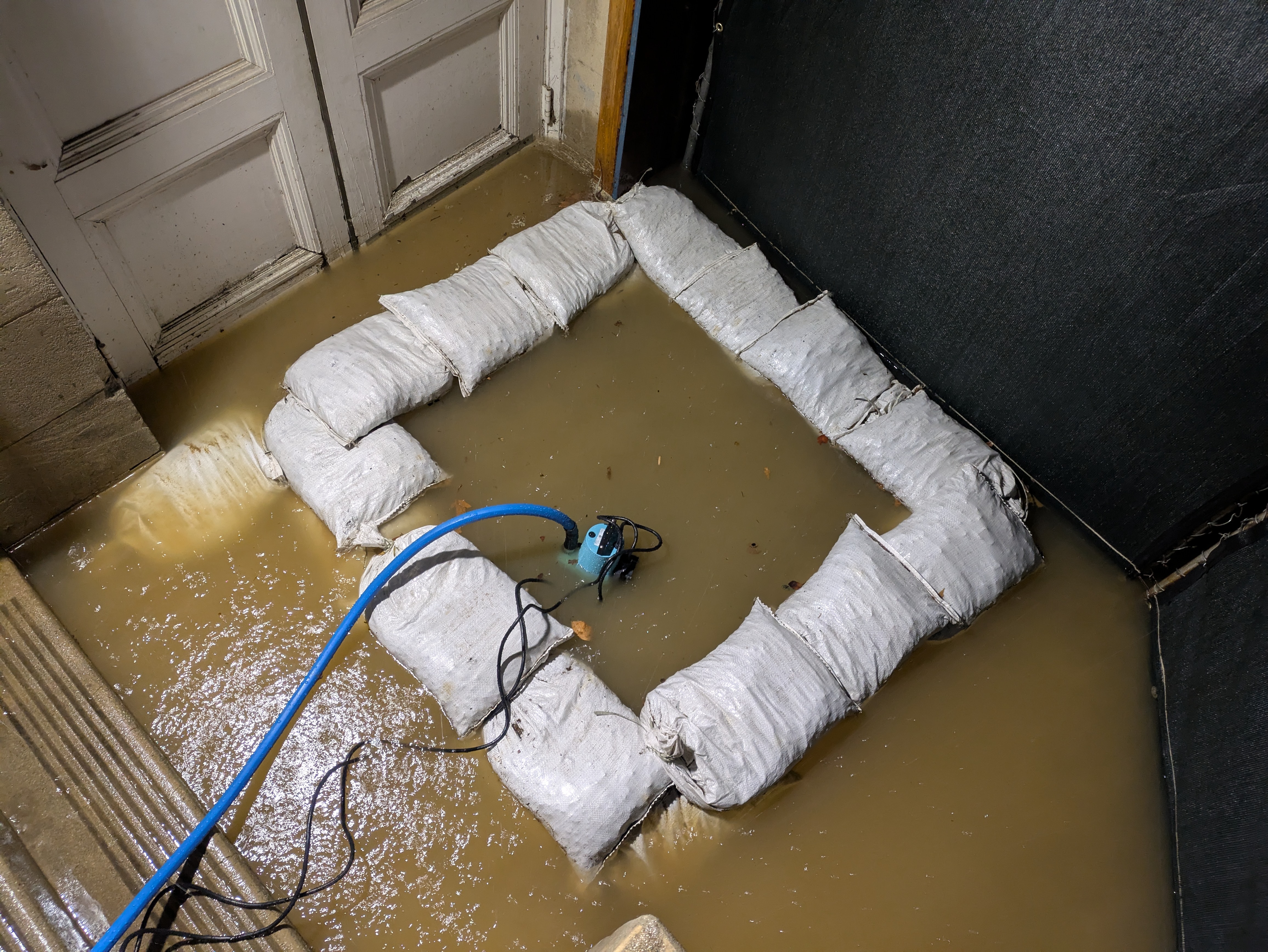
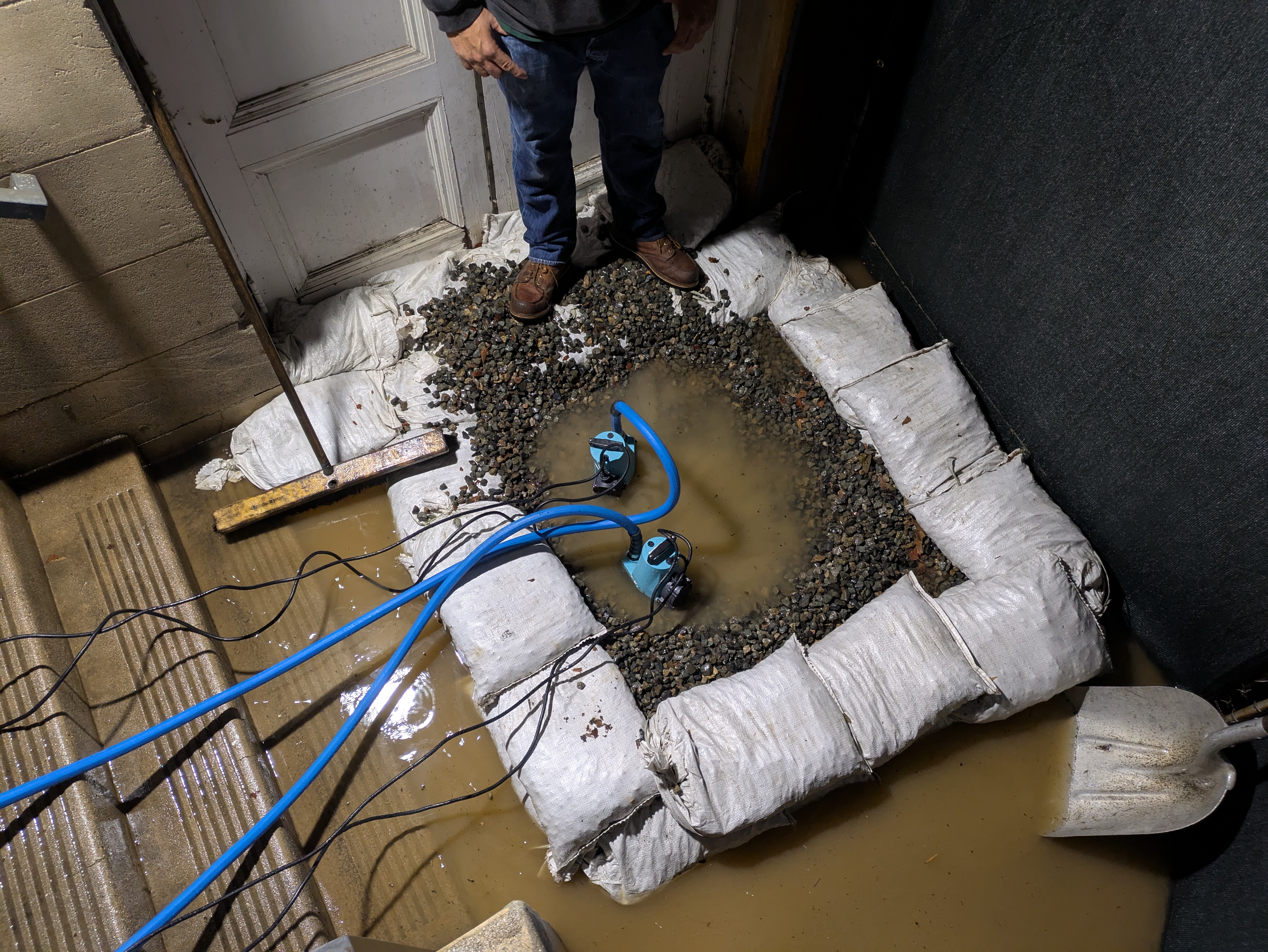
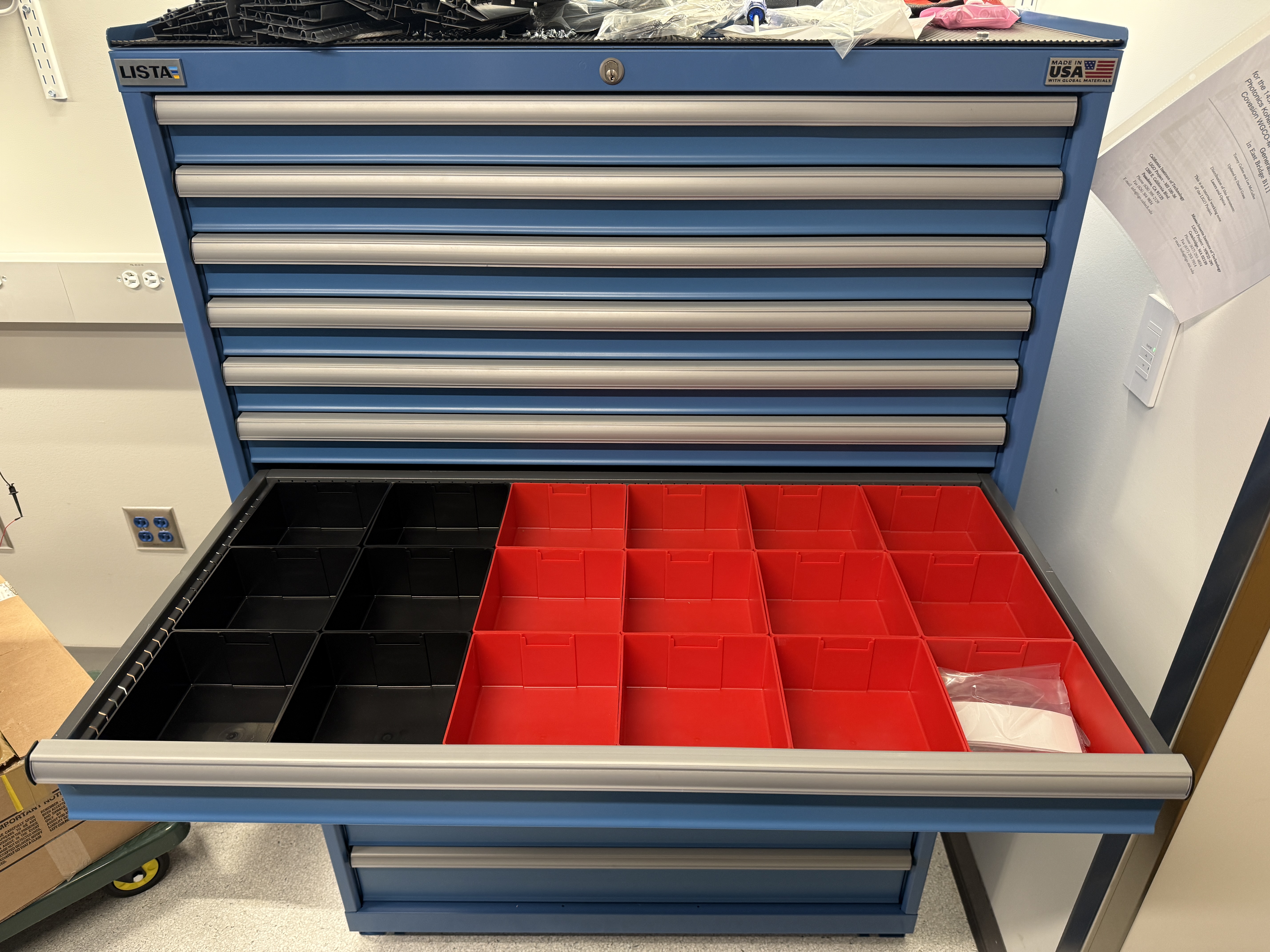
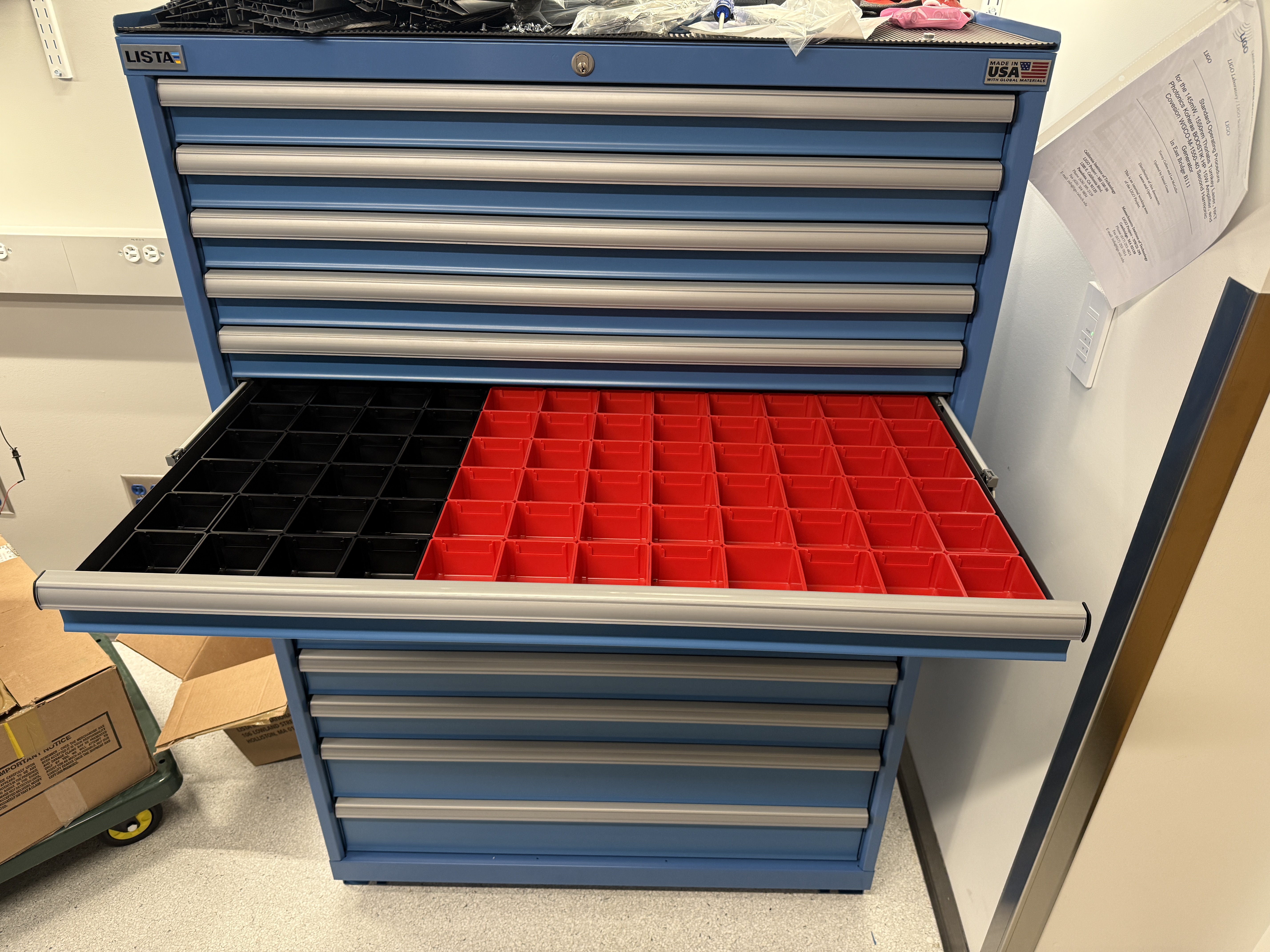
At this point, talk to the facilities staff who called in for more backup and immediately started to work to find where the water was coming from. As the water was rising, the bottom of the least of cabinets was starting to get close to the water the cabinet on the south wall of the room contains lots of important optics on the bottom drawer. I took the super optics out from the bottom drawer and moved them to the clean room in the RbQ lab. At this point, Georgia, Jeff and myself grabbed the shop vac from the mech shop and the pump room (Lab_with_shopvac.jpeg). Hoping to be able to vacuum the water up faster than it was coming into the lab. We use the vacuums to suck up water and sediment until the vacuums were filled and then we dumped the vacuums down the shower drains in the bathroom closest to the lab after about 20 minutes of this we found that we couldn't remove water faster than it was coming in as the water was still rising so we temporarily halted. We continued to remove furniture and things that were on the ground and place them either in the RB lab or in the hallway. We removed most furniture that was not tables, server racks, or cabinets. At this point, the facilities staff member had found the source of the water. The door that was sealed off during the construction of the lab is lower than the ground around it and there's a drain that drains water that would collect there (Door_with_clogged_drain.jpeg). For some reason, the drain had been blocked off most likely because of the construction of the new building next to us so water had pooled there and was flowing into the lab. The facilities member got a pump and started pumping out the water (Outside_pumping.jpg). At this point Alan Rice showed up and we started to talk about how we could remove the water from the lab. Alan called in more facilities people and custodial staff.
At this point, the water had risen to its highest level in the center of the lab. There were probably 1.5 inches of water, which then extended into the EE shop all the way down, partly into the wet lab from the ease shop. It went down the hall into the pump room and was draining down the drain. There was an active flow of water from the door where the water was coming in all the way to the drain in the pump room. Along with the water was a thin layer of sediment every place that the water was. This was probably when the water was at its highest. At this point, because the water was being pumped out much less water was coming into the lab and we started using our shop vacs to clear out the water in the EE shop and pump room. After some time, we started using the shop vac to slowly drain the water out of the hallway and EE shop.
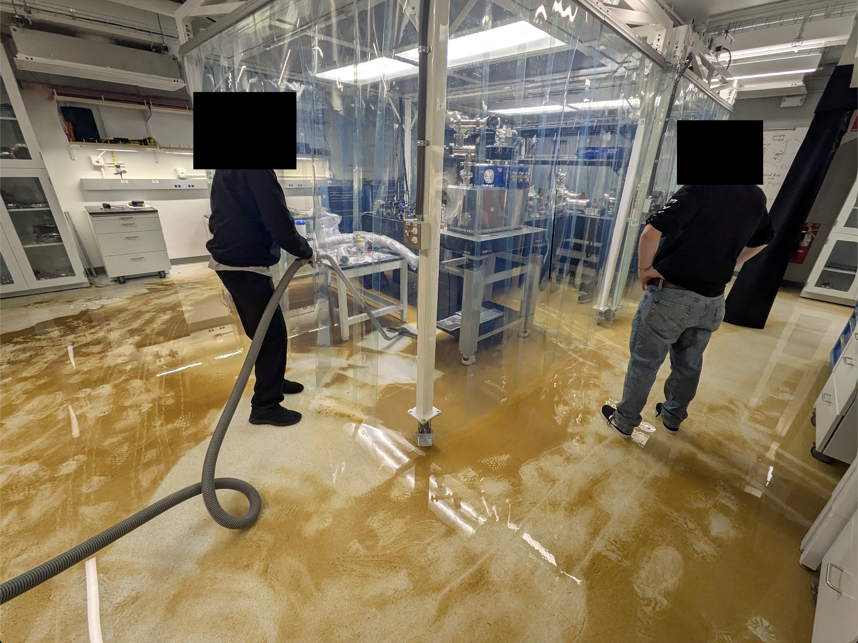
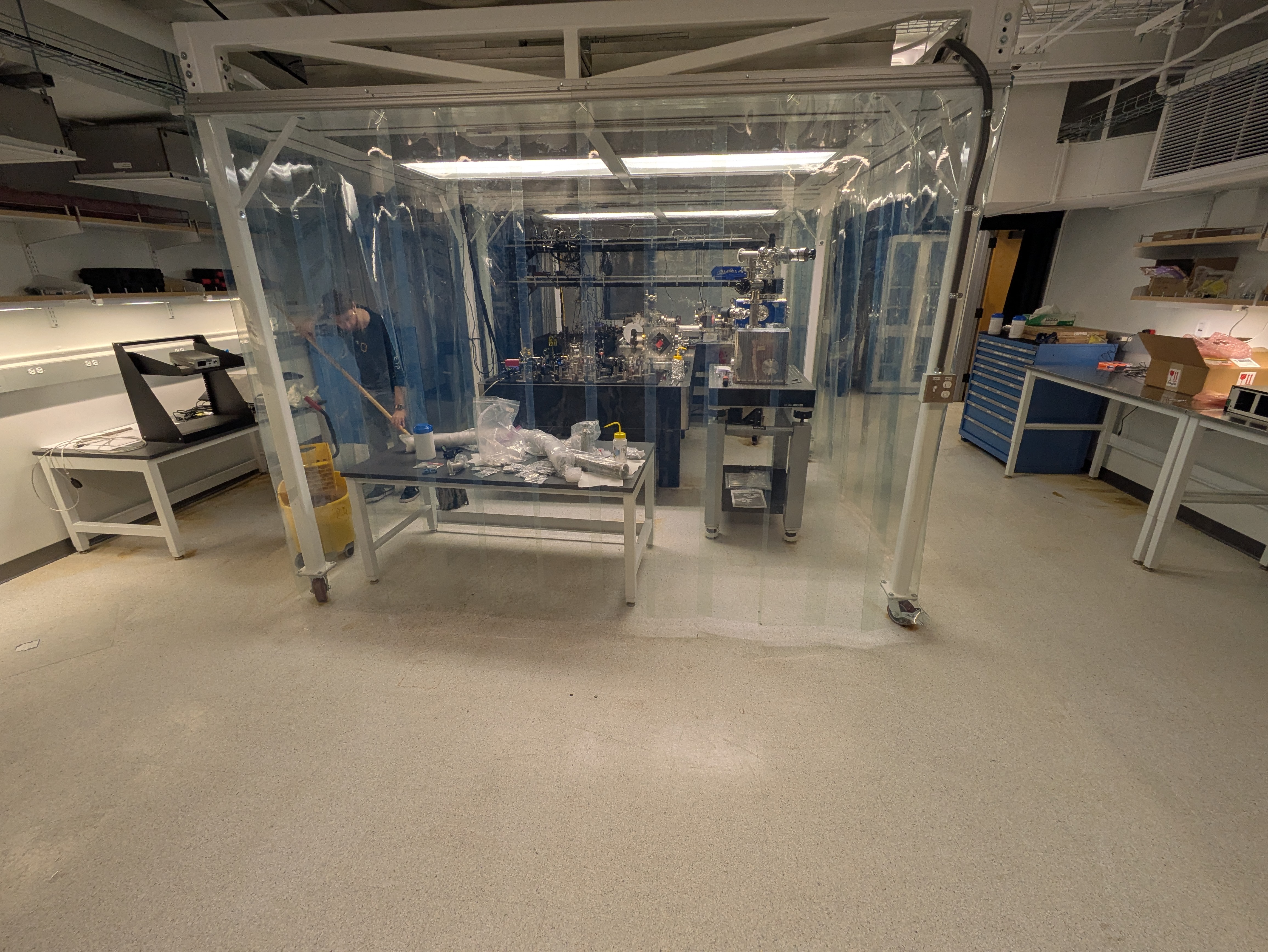
At this point (around 2 am), custodial staff showed up with industrial vacuums that were able to handle much more water. The vacuums were operated around the clean room to suck up water, but never went into the enclosure except with the head of their vacuum (Lab_Custodial_Vacuuming.png). Within a few minutes, we asked them not to go in with the heads of their vacuums. We worked with mops to pull sediment out from under the tables in the clean room enclosure for the vacuums to suck up. At this point, facilities had outdated the pool of water outside with a few pumps, and it was almost gone (Outside_pumped.jpg). Because no water was flowing in and we were vacuuming out the water, we were able to quickly remove water from the GQuEST lab. After most of the water was removed, the vacuums moved on to the EE shop, hallway, pump room, and wet lab. While they vacuumed out the other rooms, the custodial staff and I used mops to clean up as much sediment as we could from the area (Lab_mopping.jpg). Once as much of the sediment that could be easily removed was removed, facility staff and custodial staff had to move to the basement where a mechanical room had flooded, posing more of a threat to the building.
We also found that there was a leak coming from the ceiling above the sink in the wet lab. We think that this is a result of the original flooding from the roof of the building that found its way down through the walls and pipes to the wet lab. At the time, we put a large trashcan under it, but it would be helpful to eventually find out where this came from.
At this point, there was still a thin layer of sediment all over the floor, and since there was no water to hold it down, we were worried that any movement of the air could transport that dust onto optics on the tables. The only place this would really be of concern is in the clean room enclosure. Since HEPA filters keep positive air pressure in the cleaner enclosure. The only thing that can really get onto the optics is dust that's in the air inside of the clean room enclosure already. In order to prevent the thin layer of sediment that was on the floor inside of the enclosure from getting blown up onto the optics, I wiped down the floor of the enclosure bit by bit with paper towels. I started by using isopropyl alcohol on the tiles, but it felt like it was pulling up some sort of coating on the tiles, so I switched to water. I cleaned the floor of the enclosure in this manner, using only water as a solvent. The only part of the enclosure I missed was at the center of the optics tables and under the floor rack, which holds the amplifier. I obviously could not clean under where the optical table legs make contact with the floor because I have no way of lifting the tables. To try to clean under there I used water to try and flush and sediment out of there. I am not sure of how successful that was and how much sediment is left under the legs. Because of the cleaning, the floor of the enclosure should be relatively clean, and booties should be worn on the inside of it. After this was done, my main concern became drying out the parts of the lab that have been touched by water outside of the clean environment. I borrowed some of the HEPA filter blowers from the hallways around the building that are owned by PMA and placed them in the EE shop and the hallway outside of the pump room. The worry is that water has damaged the drywall, and to prevent mold, I wanted to dry it out.
The facilities people were able to clear out the drain (Outside_cleared.jpg) and said they would fix the drain and install infrastructure to prevent this in the future. I also included a timelapse from inside the lab that shows the water coming in. It only takes a photo once an hour so the time it is flooded is very short. More photos can be found in the flood folder on the nextcloud.
I then stayed at various facilities, and Caltech people showed up to assess the damage.
Aftermath:
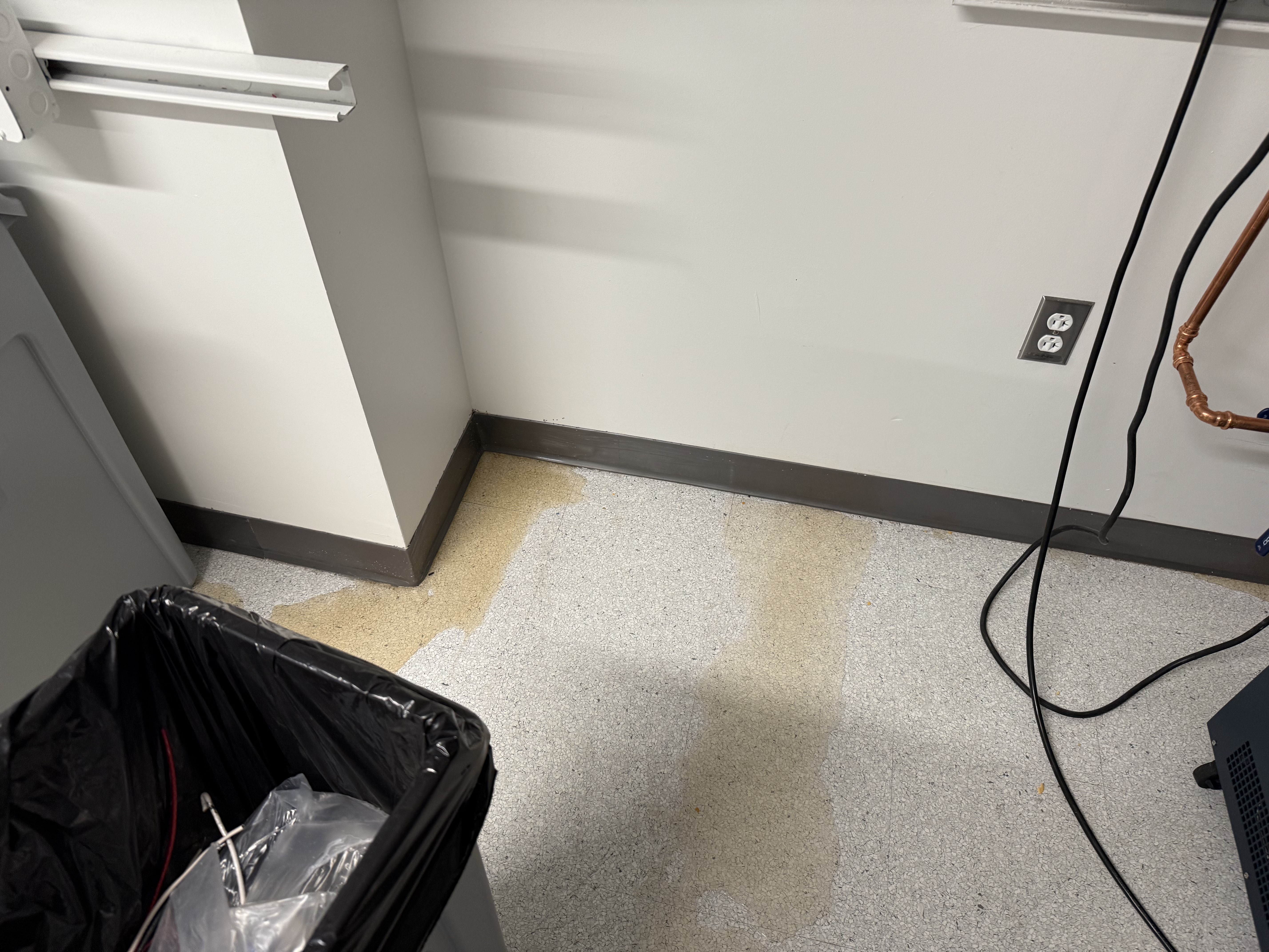
There is still sediment on the ground around the clean room enclosure. We will need to clean around the enclosure to get settlements off the ground. There is also a layer of what I assume is scum from the water that has accumulated on the tile. I'm actually not sure if this clear film that has accumulated on the tile is from the water or if it is actually from the tile and the water has caused it to become delaminated. This is something we will have to consider when we are looking at solves to clean the floor with because I'm not sure if the floor is ESD rated the floor of the clean room is relatively clean because I cleaned it with paper towels, but it still needs to undergo a thorough cleaning the floors of the EE shop, the hallway outside the pump room, the pump room and the wet lab all needs to be cleaned thoroughly in the same manner. We also should probably lift up cabinets and shelves to get all of the sediment out from under them.
Facilities will also probably want to come in and patch up the door that was leaking to access this door. They will probably have to rip a hole in the drywall and that will create lots of dust. In addition to fixing the door anytime drywall is exposed to water. It should generally be replaced and so as part of the lab fixing, they will probably want to replace the bottom 16 inches of drywall anywhere that the water was close to this will be most of the GQuEST lab as well as the pump room.
Affected Equipment:
This is a list of the equipment that is affected by the flood. It is by no means an exhaustive list.
This is the worksheet we must fill out now for items ordered and shipped from China.
Here is what I have gathered on how to fill it out:
(Also available on Wiki)
The Lista Cabinets are outfitted with boxes for storing electronics.
The red boxes can hold any component you would like but the black ones are rated for ESD-sensitive components.
Please use accordingly.
Attatched is also a quote and link to the openproject if more are needed to be ordered. The quote incudes enough small 3x3 boxes for 2 drawers of red 1 drawer of black, and the same for the larger 6x6 boxes.
[Jeff, Daniel]
We added a 10" to 4.5" CF Zero Length Reducer Flange to what will be the south side of the Laser Filter Cavity (LFC) Input Vacuum Cube. We did a bit of cleaning of the cube face before placing the flange and gasket. We moved a 10" to 2.75" CF Zero Length Reducer Flange from the LFC Cube to the input side of the Demonstrator Interferometer (IFO), also after some cleaning of the cube face. We initially hand tightened the screws when the flange wasn't properly seated, but we loosened the screws to properly place the flange. I tightened the top and side of the LFC Vacuum Cube to 13.6 Nm twice and the IFO Vacuum Cube to 13.6 Nm once. I will finish tightening these 3 flanges later.
I tightened these flanges. The top flange of the LFC input vacuum cube, which used holes that Ian and I tapped, only required 27 Nm and fewer turns than usual. I think this is because I am lightly tapping the threads in other cases. The other two flanges required 34 Nm. Like in other cases, these two flanges are not flush around the entire cube.
[Sander, Daniel]
We met with Rodica Martin of LIGO to image our silicon optics from Knight Optical using some sort of 4D Technology instrument that we have previously used. We want to evaluate whether they need to be "super-polished" or if their surface quality is good enough as is to be coated. A rough surface is problematic as it scatters light into higher order spatial modes. The loss due to scattered light from surface roughness is roughly [1,2]
\[ \text{Loss} = (2 k \cdot \text{rms})^2 = \frac{16 \pi^2 \text{rms}^2}{\lambda^2}. \]
where k is the wavenumber of the laser light with wavelength \lambda, rms is the root mean squared surface roughness. The factor of 2 in the middle expression comes from light being reflected. Given a rough budget of 10 parts per million (ppm) due to surface roughness and a wavelength of 1550 nm, this sets a maximum rms surface roughness of 0.4 nm = 4 Å.
We imaged the front and back of 5 optics: two spoked optics with an octagonal barrel, two spoked optics with a cylindrical barrel, and a cylindrical optic without spokes.
We labeled and collected the data from the optics and will formally analyze it at a later date. We could not image all of the optics in our 3 hours because it took 10 to 15 minutes to set up the optic and get a good reading.
The initial data indicated an rms surface roughness of 0.25 nm +/- 0.1 nm over a 4.5 x 4.5 mm square sample in the middle of the optical faces. The cylindrical optic without spokes was closer to 0.45 nm, we think because it is dirty (it looks dirty). Rodica said machine is limited to 0.1 nm, so the results might be even better. This would indicate consistency in our samples and no need to polish further.
Just a note: whenever you set up a new computer only use a local account. Do not set it up with a microsoft365 account (specifically, the account tied to gquestlab@gmail.com)
The microsoft365 accounts do strange things to permissions that are very annoying. In particular it makes it so that you cannot create startup tasks that can boot VMs. We will end up having to disconnect from the account, which can be a hassle since it can break things.
Only recently found this out. Please don't use microsoft accounts on any of the windows logins for the future. I'm going to remove it from Gouy which has it. Brewster does not. Not sure about other machines.
Making instructions for setting up VMs at https://wiki.mccullerlab.com/Main/VMSetupInstructions
some of the special or custom instructions will be in this comment. Editing the wiki pictures is a bit easier so I'm doing it there. Will keep editting this and adding comments as I adjust things.
[Jeff, Torrey]
We want to try Koji's way of locking a cavity that allows for testing directly at the error point. This is done in MIM on the moku but using a LIA and LLB as the two slots. We set this up and observed a very funky looking error signal, which can be interpreted as an input misalignment. This was fixed. We locked with the laser and took a spectrum at the error point directly and at the control signal. We can confirm they differed by the controller. There were some peaks that were unique to the controller that disapeared/moved around depending on the span of the spectrum.
We then retook transfer functions with a laser lock and piezo lock now that we can probe the error point directly. We are able to get better information for the TF at low frequencies with this method.
Lastly there is some funny business happening in the error signal while the cavity is locked that we notice. It looks like wave packets and is periodic.
The RF power amplifier chassis has been fixed and installed in the rack with the other chassis. There was a poor solder connection on the wire that draws current from the power supply. We are ready to AOM a 4th beam for the 4th cavity.
In order to get 775 light now that the teraxion laser is seeding the amplifier the SHG has to be tuned to the correct temperature. This is done through the covesion temperature controller program. I cannot for the life of me find where to download this from their website. Luckily I copied it from the NUC (gouy computer) and put it on the lab laptop. Then I can plug into the temperature controller without stringing up a new USB extension. I maximized the output power of the SHG by changing the temperature controller set point. The proper temperature for the TeraXion is 61.385 degrees celcius. When swapping back to the thorlabs laser the temperature should be 50.49 (this should be double checked before, haven't looked at this in a while).
[Alex, Daniel]
We started assembling the SNSPD Dewer Vacuum System Components, including the pressure gauge, the pressure relief valve, two manual valves, and a blank that can be used for leak checking or an RGA in the future. We still need to connect the vacuum hose to the SNSPD Dewer and to the KF50 to CF 4.5" Adaptor Flange and attach this flange to the Agilent Turbo Pump.
While threading in the screws to attach the Agilent FRG702 CF 2.75" Pressure Gauge to the 2.75" CF to KF16 Adapter, we accidentally pushed the included magnet away with the screws because the magnet is so close to the flange. We were able to move the magnet mostly back into place, but in the process we magnetized a 7 mm wrench used to loosen the screw that holds a clip to secure the magnet.
We might be able to use 1.25" long screws in the future to avoid this problem, but they seems a bit too short. 1.25" long screws might be the standard for CF 2.75" Flanges (with through holes on both flanges). 1.375" long screws are a possibility, but the only place I found 12-point head, 1.375" long screws was Kurt J Lesker for $37.35 each. At least these are silver plated.
Moving the magnet might be required for installing the pressure gauge into a tapped flange.
[Jeff, Sander, Torrey]
We set out to get transfer functions and noise spectra to try and diagnose the poor locking quality of the OFCs. We starting out testing how the excitation strength effected the TF. We found that anything above 1 mV (which is the minimum excitation strength) yields different results, implying this is too strong of an excitation strength. To get around this, you can add an attenuation in the digital filter box that is being used to mix the excitation signal and control signal. We confirmed this worked by recording the same TFs at different excitation voltages below 1 mV using this strategy: below1mVexcitation.png. All this to say we need to be careful about too much of an excitation signal when taking the following TFs. This is slightly problematic as at low frequency we are basically just measuring noise.
Next we take careful TFs of the OLG while the cavity is locked, with the piezo and (teraxion) laser individually. A few different notes from this result. First, below 2kHz is just noise, ignore this region. As Lee has alluded to in the past, we can approximate the fast controller as the shape of this TF at low frequencies. I have code to do this if we want this but am just showing the quick plot for now. Above 2 kHz we can see the piezo resonance around 13 kHz as well as a steep drop off in the phase after this.
Additionally, we have a plot of the noise spectra for each case. This shows a large peak where we think the piezo resonance is. Interestingly, it shows almost the exact same noise below this feature. Small note of the disconnect in the data around 10kHz. We took this data in smaller windows to get more detail in the noise spectra. Unsure why this disconnect happened.
A few other notes: The controller shape while taking this data for the piezo and laser was a pure integrater with a UGF of 40 and 100 Hz respectively. These transfer functions and noise spectra were taken using similar multi-instrument mode in the past. The data for these can be found at "\Nextcloud\GQuEST\Measurement Data\Feb4 Teraxion TF\".
We'd like to discuss with the group on next steps.
I removed the 10" to 4.5" reducer flange from the top of the Laser Filter Cavity (LFC) Input Vacuum Cube and placed it on some UHV Foil. I noticed quite a bit of chips from tapping the holes in the vacuum cube that secure the top CF flange. I removed them in 3 steps with the pre-wetted isopropanol wipes: first I removed the chips outside the copper gasket with the gasket in place, then I removed the gasket and wiped the inside ring with a wipe, then I did a final clean of the ring with a third wipe. See the attached photos of the wipes. There was considerable gunk I removed with these wipes that I have never seen before. This could be from the tapping process, but I'm not sure what specifically would cause this. A TiCN coated high speed tool shouldn't do this, nor should the chips generated. A few chips fell into the vacuum chamber but I removed the ones I could see with a fresh wipe.
Once the vacuum chamber was cleaned such that no more residue was picked up by the wipes, I added a new copper gasket (the old one was partially compressed and likely dirty) and a 10" blank flange. I screwed in the 1.75" screws to finger tight on the flange, but they still need to be tightened.
The fix was to add the internal IP address of the nas 192.168.248.15 to the lab DNS. Now
PS C:\Users\gquest> ping nxc.mccullerlab.com
Pinging nxc.mccullerlab.com [192.168.248.15] with 32 bytes of data:
Reply from 192.168.248.15: bytes=32 time<1ms TTL=64
Also added
nas.lab, docs.mccullerlab.com, files.mccullerlab.com to this IP address.
[Daniel, Sander, Torrey]
This is a continuation of this post.
We figured out how to modulate the teraxion laser. TLDR: You must enable the internal frequency locking system before the LXM-U will allow you to externally modulate. This is done through the LXM-Control software. You know it is locked when the software says its locked.
A quick few couple of tests we performed:
1) We cannot scan over a full FSR of the OFCs on this laser with 1550 light. The spec sheet says we should be able to (.2 GHz scan range at max amplitude of +/- 2.5 volts, .2 GHz > FSR).
2) We wanted to adjust the nominal wavelength of the laser to match the thorlabs so that we don't have to adjust the temperature controller of the SHG. We did not actually test this as the manual suggests we will only be change it by +/- .2 nm (and the nominal wavelength is 1551.21nm).
3) I performed the same test as in the above linked post. This shows a similar ringing up when the controller is too higher, but at a slightly different frequency. There is also a similar more broadband increase in noise as the controller gain increases.