Making instructions for setting up VMs at https://wiki.mccullerlab.com/Main/VMSetupInstructions
some of the special or custom instructions will be in this comment. Editing the wiki pictures is a bit easier so I'm doing it there. Will keep editting this and adding comments as I adjust things.
[Jeff, Torrey]
We want to try Koji's way of locking a cavity that allows for testing directly at the error point. This is done in MIM on the moku but using a LIA and LLB as the two slots. We set this up and observed a very funky looking error signal, which can be interpreted as an input misalignment. This was fixed. We locked with the laser and took a spectrum at the error point directly and at the control signal. We can confirm they differed by the controller. There were some peaks that were unique to the controller that disapeared/moved around depending on the span of the spectrum.
We then retook transfer functions with a laser lock and piezo lock now that we can probe the error point directly. We are able to get better information for the TF at low frequencies with this method.
Lastly there is some funny business happening in the error signal while the cavity is locked that we notice. It looks like wave packets and is periodic.
The RF power amplifier chassis has been fixed and installed in the rack with the other chassis. There was a poor solder connection on the wire that draws current from the power supply. We are ready to AOM a 4th beam for the 4th cavity.
In order to get 775 light now that the teraxion laser is seeding the amplifier the SHG has to be tuned to the correct temperature. This is done through the covesion temperature controller program. I cannot for the life of me find where to download this from their website. Luckily I copied it from the NUC (gouy computer) and put it on the lab laptop. Then I can plug into the temperature controller without stringing up a new USB extension. I maximized the output power of the SHG by changing the temperature controller set point. The proper temperature for the TeraXion is 61.385 degrees celcius. When swapping back to the thorlabs laser the temperature should be 50.49 (this should be double checked before, haven't looked at this in a while).
[Alex, Daniel]
We started assembling the SNSPD Dewer Vacuum System Components, including the pressure gauge, the pressure relief valve, two manual valves, and a blank that can be used for leak checking or an RGA in the future. We still need to connect the vacuum hose to the SNSPD Dewer and to the KF50 to CF 4.5" Adaptor Flange and attach this flange to the Agilent Turbo Pump.
While threading in the screws to attach the Agilent FRG702 CF 2.75" Pressure Gauge to the 2.75" CF to KF16 Adapter, we accidentally pushed the included magnet away with the screws because the magnet is so close to the flange. We were able to move the magnet mostly back into place, but in the process we magnetized a 7 mm wrench used to loosen the screw that holds a clip to secure the magnet.
We might be able to use 1.25" long screws in the future to avoid this problem, but they seems a bit too short. 1.25" long screws might be the standard for CF 2.75" Flanges (with through holes on both flanges). 1.375" long screws are a possibility, but the only place I found 12-point head, 1.375" long screws was Kurt J Lesker for $37.35 each. At least these are silver plated.
Moving the magnet might be required for installing the pressure gauge into a tapped flange.
[Jeff, Sander, Torrey]
We set out to get transfer functions and noise spectra to try and diagnose the poor locking quality of the OFCs. We starting out testing how the excitation strength effected the TF. We found that anything above 1 mV (which is the minimum excitation strength) yields different results, implying this is too strong of an excitation strength. To get around this, you can add an attenuation in the digital filter box that is being used to mix the excitation signal and control signal. We confirmed this worked by recording the same TFs at different excitation voltages below 1 mV using this strategy: below1mVexcitation.png. All this to say we need to be careful about too much of an excitation signal when taking the following TFs. This is slightly problematic as at low frequency we are basically just measuring noise.
Next we take careful TFs of the OLG while the cavity is locked, with the piezo and (teraxion) laser individually. A few different notes from this result. First, below 2kHz is just noise, ignore this region. As Lee has alluded to in the past, we can approximate the fast controller as the shape of this TF at low frequencies. I have code to do this if we want this but am just showing the quick plot for now. Above 2 kHz we can see the piezo resonance around 13 kHz as well as a steep drop off in the phase after this.
Additionally, we have a plot of the noise spectra for each case. This shows a large peak where we think the piezo resonance is. Interestingly, it shows almost the exact same noise below this feature. Small note of the disconnect in the data around 10kHz. We took this data in smaller windows to get more detail in the noise spectra. Unsure why this disconnect happened.
A few other notes: The controller shape while taking this data for the piezo and laser was a pure integrater with a UGF of 40 and 100 Hz respectively. These transfer functions and noise spectra were taken using similar multi-instrument mode in the past. The data for these can be found at "\Nextcloud\GQuEST\Measurement Data\Feb4 Teraxion TF\".
We'd like to discuss with the group on next steps.
I removed the 10" to 4.5" reducer flange from the top of the Laser Filter Cavity (LFC) Input Vacuum Cube and placed it on some UHV Foil. I noticed quite a bit of chips from tapping the holes in the vacuum cube that secure the top CF flange. I removed them in 3 steps with the pre-wetted isopropanol wipes: first I removed the chips outside the copper gasket with the gasket in place, then I removed the gasket and wiped the inside ring with a wipe, then I did a final clean of the ring with a third wipe. See the attached photos of the wipes. There was considerable gunk I removed with these wipes that I have never seen before. This could be from the tapping process, but I'm not sure what specifically would cause this. A TiCN coated high speed tool shouldn't do this, nor should the chips generated. A few chips fell into the vacuum chamber but I removed the ones I could see with a fresh wipe.
Once the vacuum chamber was cleaned such that no more residue was picked up by the wipes, I added a new copper gasket (the old one was partially compressed and likely dirty) and a 10" blank flange. I screwed in the 1.75" screws to finger tight on the flange, but they still need to be tightened.
The fix was to add the internal IP address of the nas 192.168.248.15 to the lab DNS. Now
PS C:\Users\gquest> ping nxc.mccullerlab.com
Pinging nxc.mccullerlab.com [192.168.248.15] with 32 bytes of data:
Reply from 192.168.248.15: bytes=32 time<1ms TTL=64
Also added
nas.lab, docs.mccullerlab.com, files.mccullerlab.com to this IP address.
[Daniel, Sander, Torrey]
This is a continuation of this post.
We figured out how to modulate the teraxion laser. TLDR: You must enable the internal frequency locking system before the LXM-U will allow you to externally modulate. This is done through the LXM-Control software. You know it is locked when the software says its locked.
A quick few couple of tests we performed:
1) We cannot scan over a full FSR of the OFCs on this laser with 1550 light. The spec sheet says we should be able to (.2 GHz scan range at max amplitude of +/- 2.5 volts, .2 GHz > FSR).
2) We wanted to adjust the nominal wavelength of the laser to match the thorlabs so that we don't have to adjust the temperature controller of the SHG. We did not actually test this as the manual suggests we will only be change it by +/- .2 nm (and the nominal wavelength is 1551.21nm).
3) I performed the same test as in the above linked post. This shows a similar ringing up when the controller is too higher, but at a slightly different frequency. There is also a similar more broadband increase in noise as the controller gain increases.
[Alex, Jeff]
We measured the output of the Thorlabs power supply we have for the ULN turnkey laser.
We measured it with no load and with 1.3K R (12V/1.3K = 0.01A) and saw the following IMG_1203.jpg
24Hz sawtooth, 50mV pk-pk
We wonder if this has something to do with the ground fluctuations on the DC modulation port of the laser. Is this to spec for the power supply? The data sheet mentions 100mV ripple but does not give a frequency.
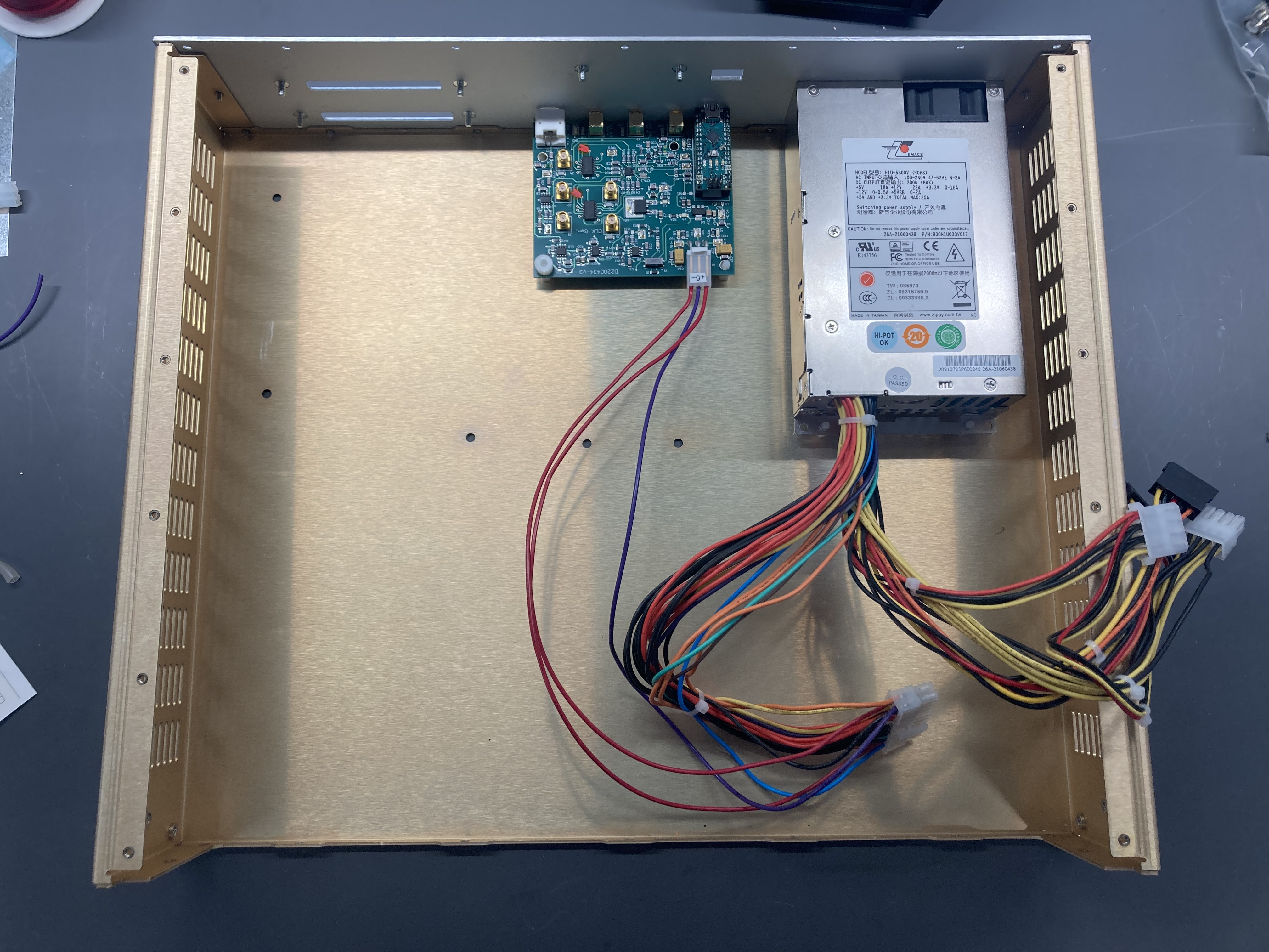
This is a continuation of LeeLog 12105. TLDR - Teraxion laser is fully installed and functioning correctly except for the modulation port required to lock a cavity.
We put the swap on hold as a result of there being no internal Faraday Isolator in the teraxion seeder. Lee mentioned this should be fine for the short term. We plan on buying an isolator soon. In the mean time we should be fine to run this test.
Notes for the swap:
-Powered down amplifier. Turned off Thorlabs seeder.
-Secured laser module to the breadboard.
-Connected the module via USB extension to the BREWSTER computer. Connected fiber output to the power meter via fiber adapter. Turned power on.
-Installed the teraxion LXM laser control GUI on the BREWSTER computer.
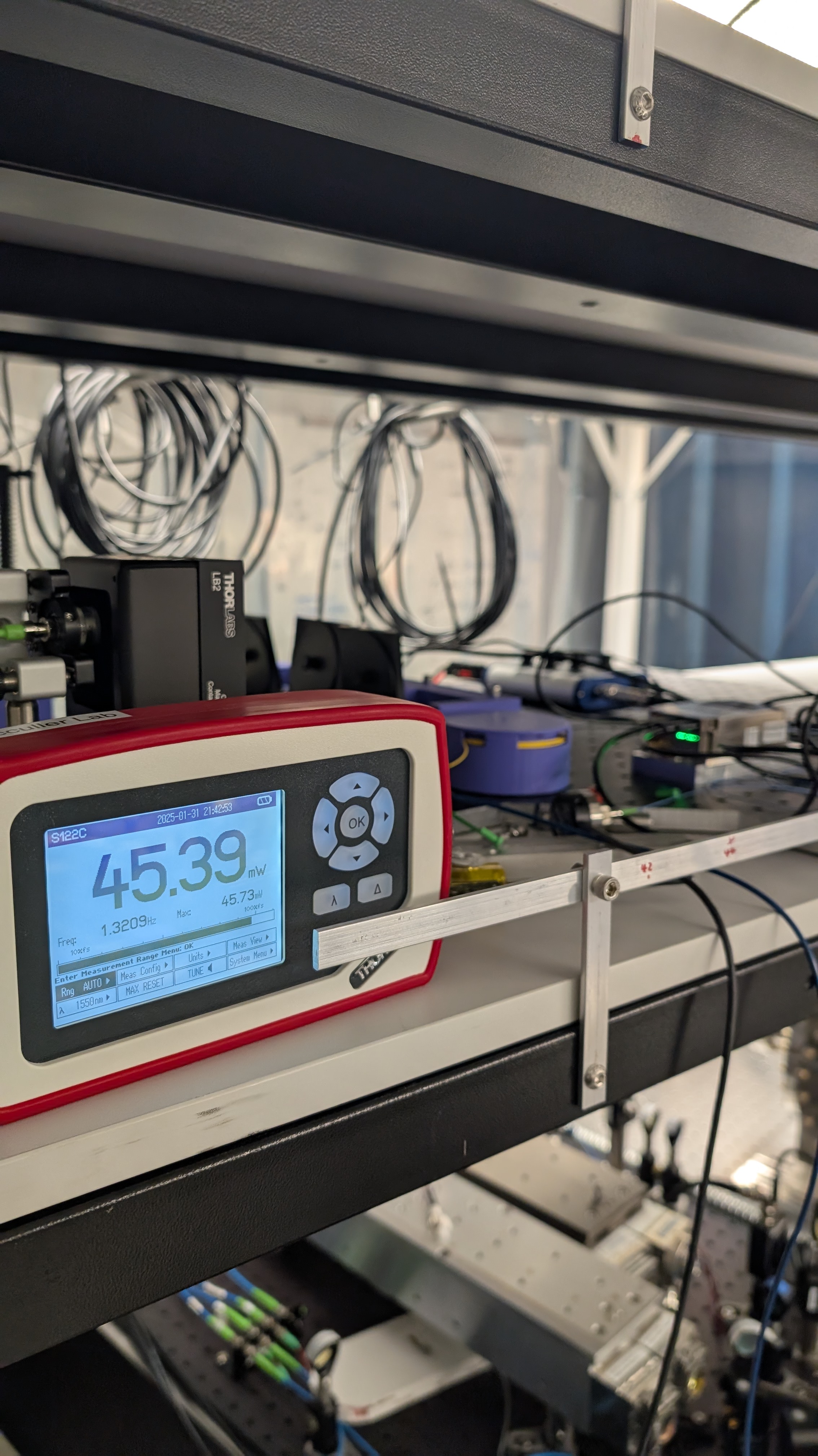
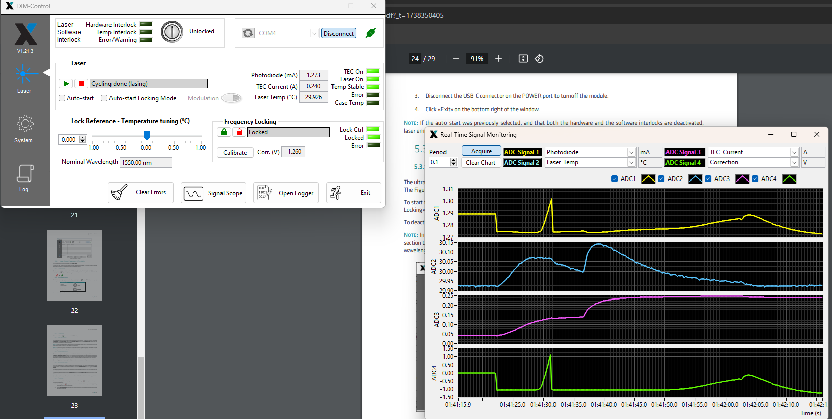
-We successfully turned on the laser via the LXM laser control software. Note the software has an interlock system with a password, this password is 1234 and can be found in the manual. The initial output of the laser is 45mW as seen in the photo. I have concerns with controlling the laser via this little GUI. I don't know how closing the program or disconnecting the USB effects the continuous operation of the laser. This is important to ensure that no damage is done to the amplifier. We may test how easy it is to disrupt operation of the laser module before connecting to the amplifier. Testing in the software, there is no "are you sure button" when disabling the output. One click disables it.
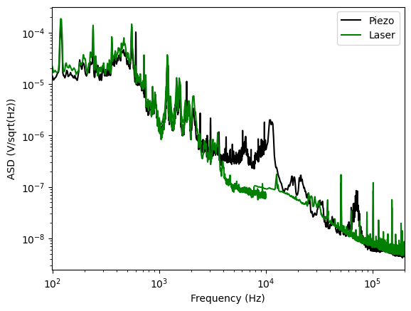
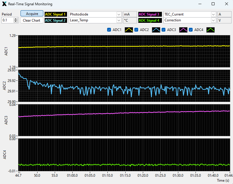
-The laser has ADCs and a popout in the software to track parameters of the laser like TEC current, laser temp, etc. See adc.png.
-I decided to test the continuous operation of the laser. Click the "Exit" button in the bottom right of the software does not disrupt lasing. I will assume that the laser will not shut down unless commands in the software are giving. This alleviates my worry outlined above.
-I plan on replacing the fiber PBS with a 75:25 fiber BS. This means one laser will have significantly reduced output. I need to double check the nominal output of the thorlabs laser to see if output*.25 is high enough to properly seed the amplifier.
-Replaced the fiber PBS with the 75:25. The output for the thorlabs seeder after the :25 path in the fiber beam splitter is ~10 mW (using the power meter, this value will change for the amplifier threshold power detector), which is most likely below the required input for the amplifier. Reminder: "Turn the Key ON: if the input power is lower than the pre-determined lower threshold power (typically 10-20 mW), there is an Alarm LIP (low Input Power), otherwise the preamplifier turns ON." Alternatively, we can swap the outputs of the fiber BS to avoid any alarms. The white output fiber should be used for the teraxion, the red output fiber for the thorlabs. Otherwise just getting one of these but a 50:50 would avoid having to ever swap any fiber connections. This is recommended.
-The teraxion is now seeding the amplifier. The power meter read 30.3 mW, the amplifier seeder is reading 27 mW. Both of the values are above the threshold. Continuing with turning on Amplifier.
-Turned key and hit enable on amplifier. The amplifier is now in pre-amplification mode. ~300 mW at the output, seeded by the teraxion.
-There is no 775 light. No light seems to be exiting the SHG. I suspect the wavelengths of the 2 lasers are different enough that the temperature controller needs to be tuned to the proper temperature for the SHG. I don't need 775 light for this test however so I will just note it and move on. Alternatively the wavelength of the laser can be tuned via a temperature controller. You most likely can tune to the same wavelength as the thorlabs controller so the SHG temperature controller doesn't have to be touched.
-The last step is we need to be able to modulate on the new laser. The manual says "please refer to the device test sheet to determine if your laser module accept ±2.5 V input or 0-4 V". Our test sheet on the wiki says +/- 2.5V. If using the moku this will never be a problem as we can't operate above +/- 2V in MIM anyways.
-Connected a moku output to the modulation port of the teraxion laser via patch panel and SMA adapter.
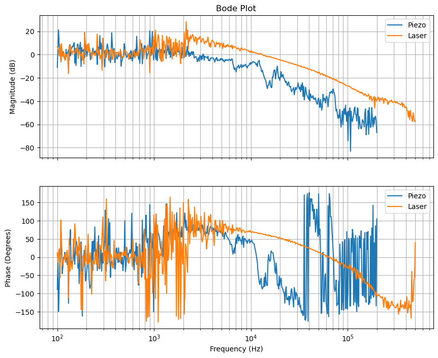
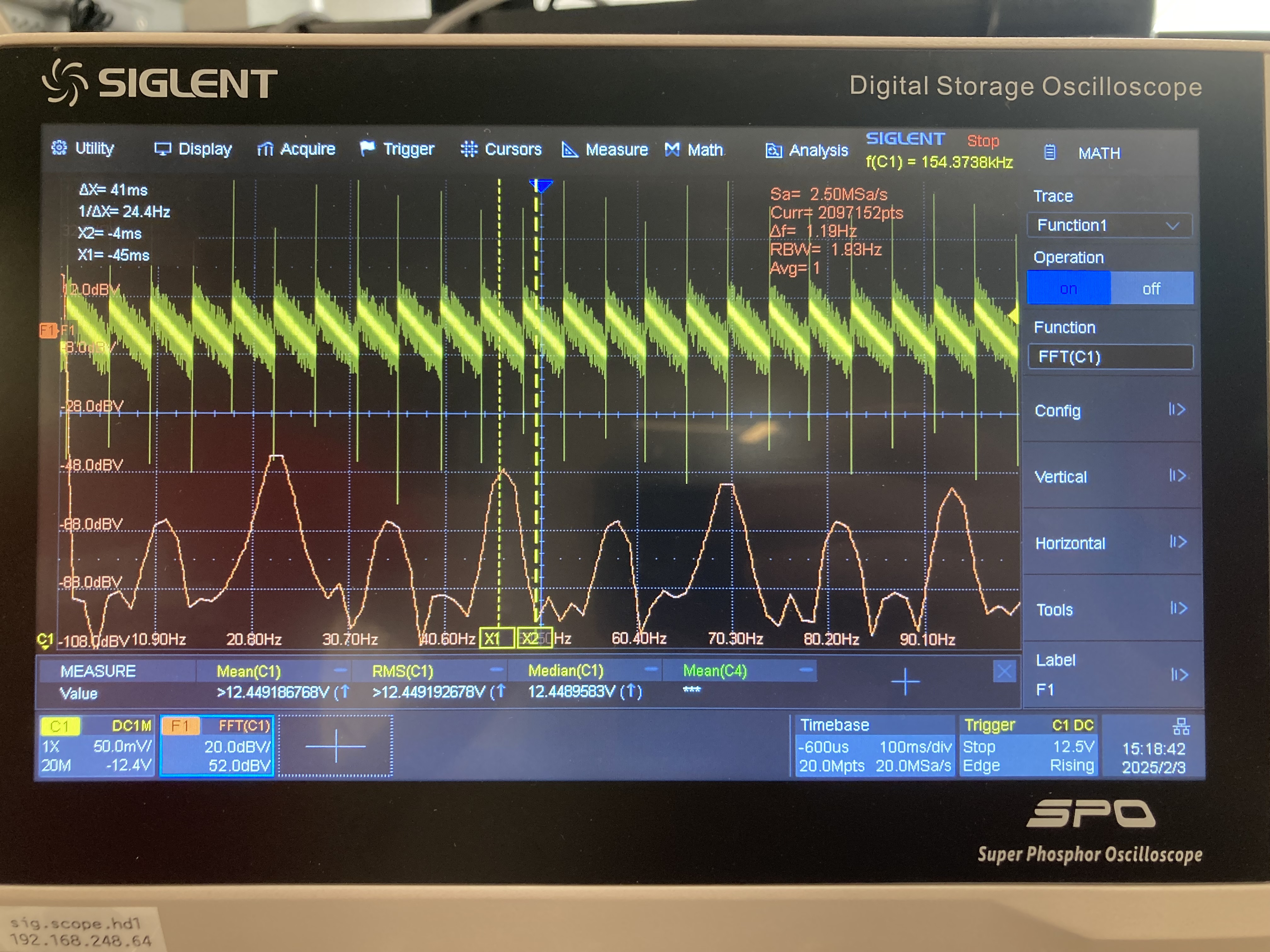
-Everything is connected. Scanning 2 V pp on the modulation port doesn't flash the cavity. I don't think anything is actually scanning. The scan amplitude is .2 GHz. The FSR is 125 MHz. Even at half the scan range we should see something. I tuned the temperature controller to have the cavity naturally flashing, and then turn on the modulation scan and still don't see anything. Manual shows a diagram connected to a waveform generator with a "10-100kHz" signal. Changed the scan frequency to this range, no change. I confirmed the moku is outputting a voltage via T-ing off the output and checking on a different scope. There is a triangle wave.
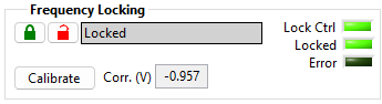
-Not sure what else to try so I checked the Ultra Narrow Linewidth Mode that is unique to the LXM-U that we have. It works.
Software download info can be found at https://wiki.mccullerlab.com/Main/MX-S24007
I moved one set of tools on to the small blue cart and into the GQuEST lab. This should have all of the basic tools and any specialty tools that you use in the lab can be put in here if you find yourself having to go to the maker space to get them. Please don't go into the maker space to get a tool unless you are certain that it is not in the small tool box in the lab. Please don't move tools between the two spaces unless it is temporary. If there is anything we need for the small lab tool box please let me know.
After refitting the base of the drill press, I attached it to the table with the previously purchased hardware. I made special care not to over tighten it and secured the bolts with loctite. I also was able to drill the last hole through the table for the vice. It goes through the metal frame. I also realized that that table top is not attached to the legs in the proper way. It seems like whoever built it just used silicone to stick them together. There are holes for screws to attach the table to the table top. They should have done that. It seems like all the tables have this problem. It is possible for the vibrations from the drill press or movement from the vice to separate the table top from the legs. They should come back and fix it.
[Jeff, Torrey]
The background for this is we have noticed 10's of kHz ringing up in the timeseries of the error signal when the gain on the fast controller gets too high. On the computer app where we can control multiple instruments at once we have increased the gain and taken spectrums while the cavity is locked. The plan is to do this for the thorlabs laser and the teraxion laser and compare the two. We are waiting on an optical isolator to conduct the teraxion half of this experiment, in the mean time here is the thorlabs laser data.
The following data is for locking OFC1, with the thorlabs laser, while controlling from the computer app. thorlabslaservaryingcontrollergain.png are the results. We can see a clear increase in the noise around 20 kHz as the controller gain is increased. It will be interesting to see if a similar feature is there when using the teraxion laser. Note the controler UGFs are listed between 2-18 hz, but there are several gain increases between the controller and the laser, so they should not be taken as the UGF of the whole loop.
We still plan on taking TF's instead of this analysis. For now, the smallest excitation strength on the moku (1mV) is too large. We are working on this.
[Ian, Daniel]
We tapped all 24 holes to secure the 10" flange on top of the Laser Filter Cavity (LFC) Input Vacuum Cube with the cleaned 5/16"-24 taps using some isopropanol as a lubricant. I used a 7 mm 12-point wrench. While its ~3" length made me apply more force to tap, I felt like it reduced the change of breaking a tap. We kept a 10" flange on top so that the vacuum system wasn't exposed. The taps fit within the holes of the flange. Before tapping, screws could only get 3 turns in by hand before encountering a lot of resistance. We used the tappered tap, plug tap, and bottom tap, going all the way to the bottom. The tappered tap went up 14 revolutions and the bottom tap went up 17 revolutions after tapping. The 1.75" long screws easily went into the holes after the plug tap and bottom tap. We used the bottom tap to ensure the screws wouldn't encounter any resistance when the flange is tightened. Some metal chips were generated. Some came out with the taps, some are surely in the bottom of the holes.
The TiCN coating might have been slightly removed by the end of tapping. The color might be different and the tapping may have gotten harder, but this is somewhat subjective.
Context: I am following the instructions of LIGO DCC document E2300448-v2 to assemble the main chassis of our 'standard' cymac, named Babbage.
See D2300234-v1 for instuctions.
Notes:
I borrowed a tool from Todd Etzel in Downs which allows you to remove the metal connectors from the plastic ATX sheath. Without this tool it was near impossible, and I believe I made the job much harder for myself by trying to simply yank the wires out. I reccomend you do not attempt to remove wires from an ATX connector without one of these tools.
After this the process was straightforward, and described resonably well in the document above.
I cleaned some 5/16"-24 TiCN coated High Speed Steel Taps for use around UHV. These taps are stronger and more durable than the taps in the tap set. I did a 90 second bath and sonication in Simple Green:DI water (1:30) and noticed a few particulates come off (I don't think it's the coating as the coating looked intact, but I didn't want to risk stripping it, hence only 90 seconds). I brushed the taps, washed with DI water, did a 2 minute sonication in a DI water bath, washed with isopropanol, then did a 2 minute sonication in isopropanol.
[Jeff,Torrey]
Assorted notes:
-I completed the assembly of the piezo mirror. This required having daniel machine a custom spacer for the assembly. With the spacer, the piezo alignment tool works. Note that this new piezo has a larger OD that is large enough to prohibit the use of the nylon tipped set screws for alignment. Because of this the spacer and piezo may not be concentrically aligned to the mirror.
-Installed a 2 meter 780 PM fiber at the OFC2/OFC3 sled fiber port hub. This allows a connection from the third AOM path to OFC3 775 input.
-We are going to start mode matching into cavity 3. The USB extension from the NUC computers does not recognize the scanning slit beam profiler. This is probably due to the USB extension being over 100 ft and needing external power. We are going to use the new lab laptop for now instead.
-The new laptop is unusable for the scanning slit software. For some reason it is constantly crashing and freezing.
-After switching to Torrey's laptop, we collected data for the beam size between the launcher and the third filter cavity. We noticed amplitude fluctuations on the beam, but they reduced when we raised the power on this path (by turning the amplifier current to 1A. This should correspond to ~1.5W total output on the distribution center).
-We spent some time profiling and finding a mode matching solution. The waist for this light needs to be .26 meters after the collimator for this configuration which is making it difficult to mode match. We are going to try moving the collimator back tomorrow and reprofiling.
-We turned the amplifier back down until tomorrow.
After playing around in JAMMT I found that moving the collimator back would result in easy mode matching solutions. I moved the collimator back 12 inches and reprofiled. Now, according to finesse and JAMMT, a robust solution is f=2000 mm @ z=0.066, f=2500 mm @ z=0.354, (v=100 %). We have these lens. Will implement after lunch.
I put the two lens in the positions according to the above comment. I then profiled the beam after the second lens. This gives the following data below:
Horizontal Vertical
Beam waist radius[um] 402.531593 423.098793
Waist position [m] 0.148341 0.146998
Rayleigh range [inches] 25.859159 28.569197
Radius Average 412.815193
Waist Position Average 0.147669
According to finesse, and accounting for the extra two 1/8 spacers, the beam this cavity accepts is 411 um @ .106 meters after the lens. The measured quanity is 412 um .147 meters after the lens. This should yield a mode mismatch well below 1%. I will close this work for now unless we see large laguerre gauss modes in the cavity scans in the future.
I designed a plate to mount the TeraXion LXM-U Laser to the optics table with good thermal contact. I used a fly cutter at 1800 rpm to get a really nice top and bottom surface finish and a 3/4" end mill to get the sides. See attached files.
I unfortunately broke a tap in one of the mounting holes and couldn't remove it. Martin Mendez in the Chemistry Machine Shop said it would take 2-3 hours of shop time to burn through the tap with the plunge EDM, costing $120-$190. Since only 2-3 holes are needed to securely mount the laser, I cut out the hole with the broken tap with the band saw.
For the other 3 #4-40 holes, I drilled them out to 0.0935" (using a #42 drill) instead of the standard 0.089" (a #43 drill) to help with the tapping. This is still plenty of thread engagement, and the tapping went much better.
I cleaned the plate with Simple Green:DI water, DI water, and isopropanol and sonication for each step. The LXM-U fits on the #4 holes, seemingly with a great contact. One of the 1/4-20 counterbored holes isn't useful as a laser input/output blocks it, but there are still 3 holes to secure the plate.