[Jeff,Torrey]
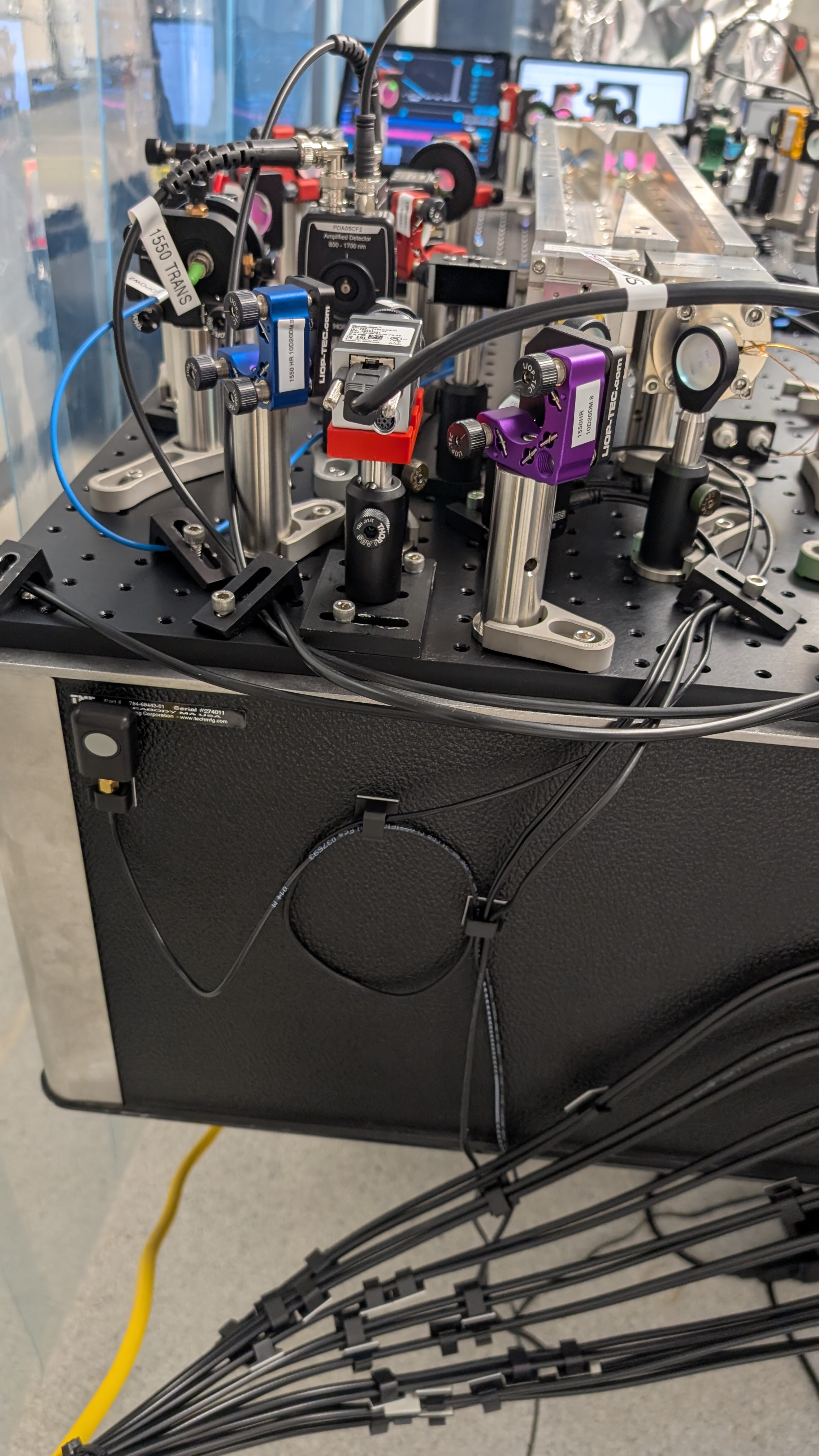
Yesterday I attenuated the input to OFC1 1550 path so TRANS PD wasn't saturated and didn't mention it so I am doing so here. This gives an input to the cavity at 4.6 mW. The output while locked is 1.22 mW. It seems as though the cavity is not particularly closed to critically coupled, although this is not suprising based on the depth of the REFL dips. We chose a lens to put the output beam of OFC1 into a fiber that will connect to OFC2 input. The measured output of this fiber was 1.06 mW, which is an efficiency just over 86%. This could be improved but for now we will keep it here. I think for this measurement as long as we know of all the optical losses along the path, we don't care if there are any. This obviously changes when we are trying to get signal photons to an SNSPD. Additional sources of losses leading into OFC2:
-FC/APC connection between two fibers ( like this ). Quoted at .5 db insertion loss.
-A 50:50 fiber beamsplitter is plugged into the other side of the mating sleeve. This was to be able to do OFC2 and OFC3 things at the same time. This will be changed eventually but keeping it for now as I think its still useful. Quoted at 3.4 dB insertion loss and then obviously a 50:50 split. In a loss calculation refer to this for more details.
-Any optical losses between fiber output and input to cavity. Should be <1%.
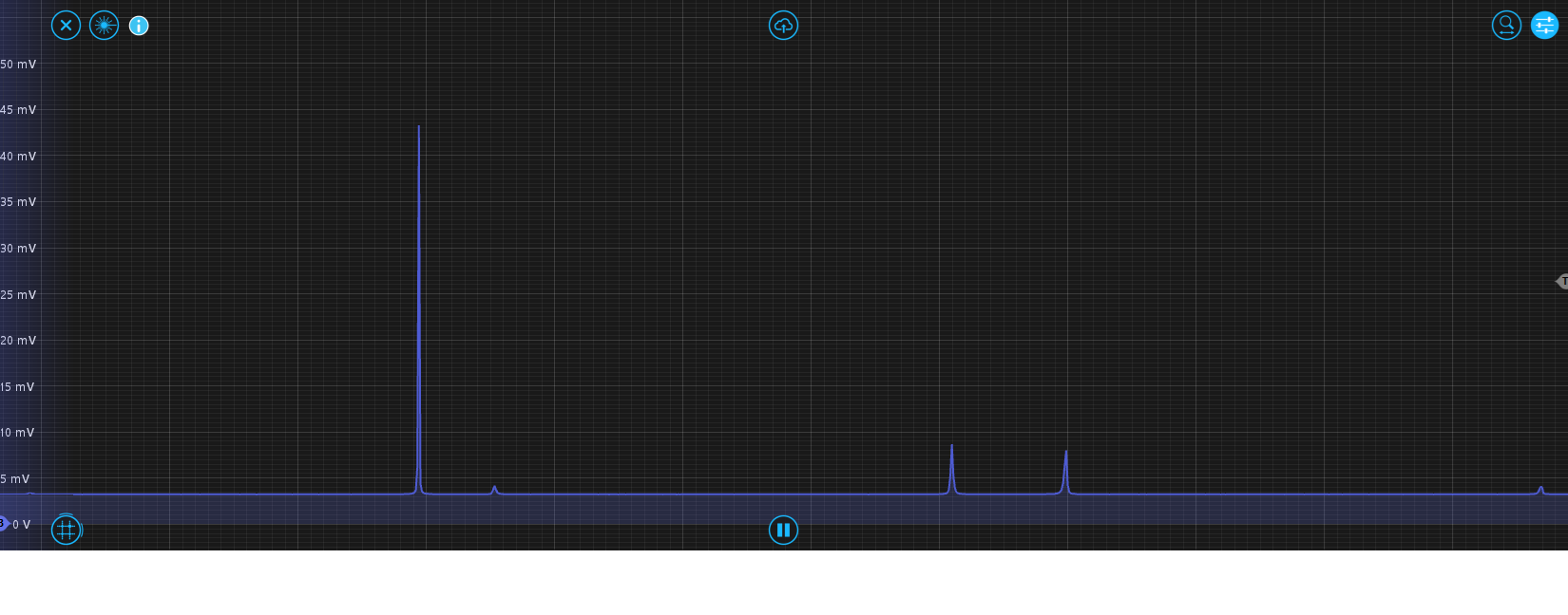
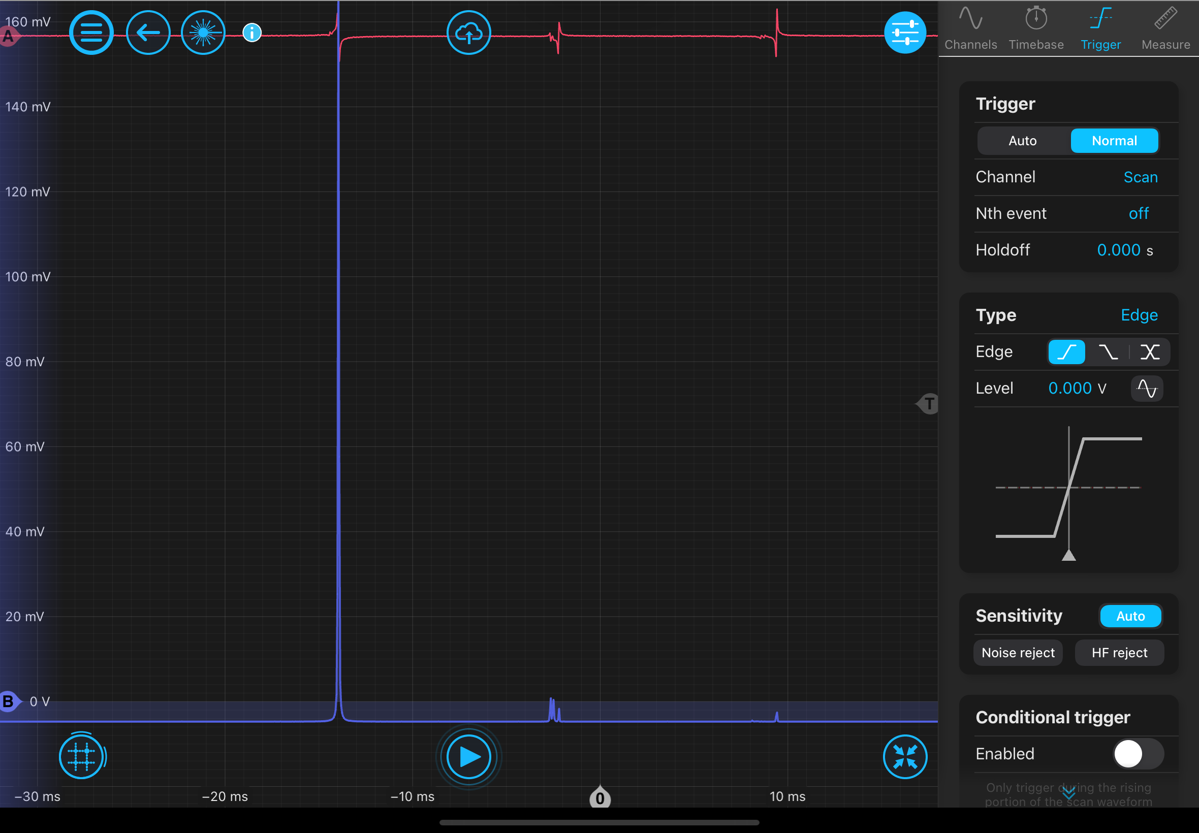
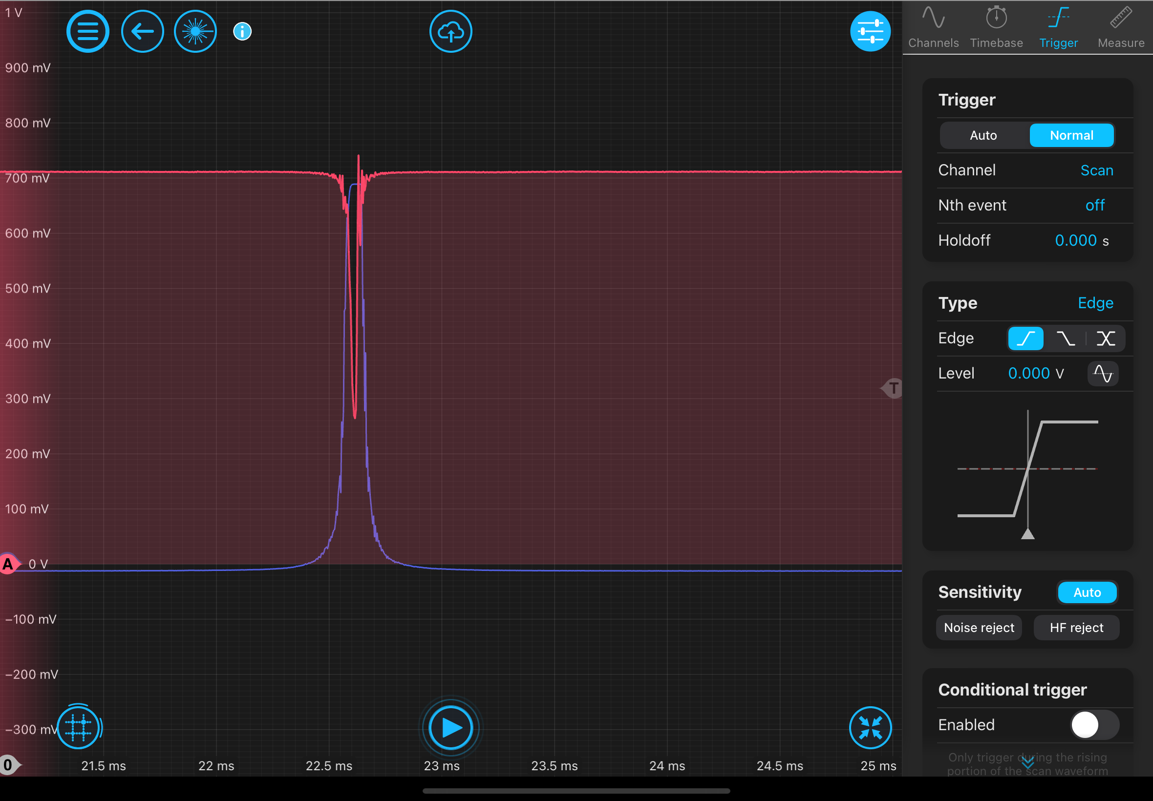
After lunch we plan on swapping the fibers out so that the OFC1 output is seeding OFC2. Before doing this we took a mode scan of OFC2 with its original seed light. This is to compare mode scans directly between swapping the fibers. More to come after lunch.