Daniel Grass - posted 11:28, Thursday 31 October 2024 - last comment - 11:31, Monday 04 November 2024(11955)
Corner Cut out of Mobile Clean Room Tile to make room for Cables
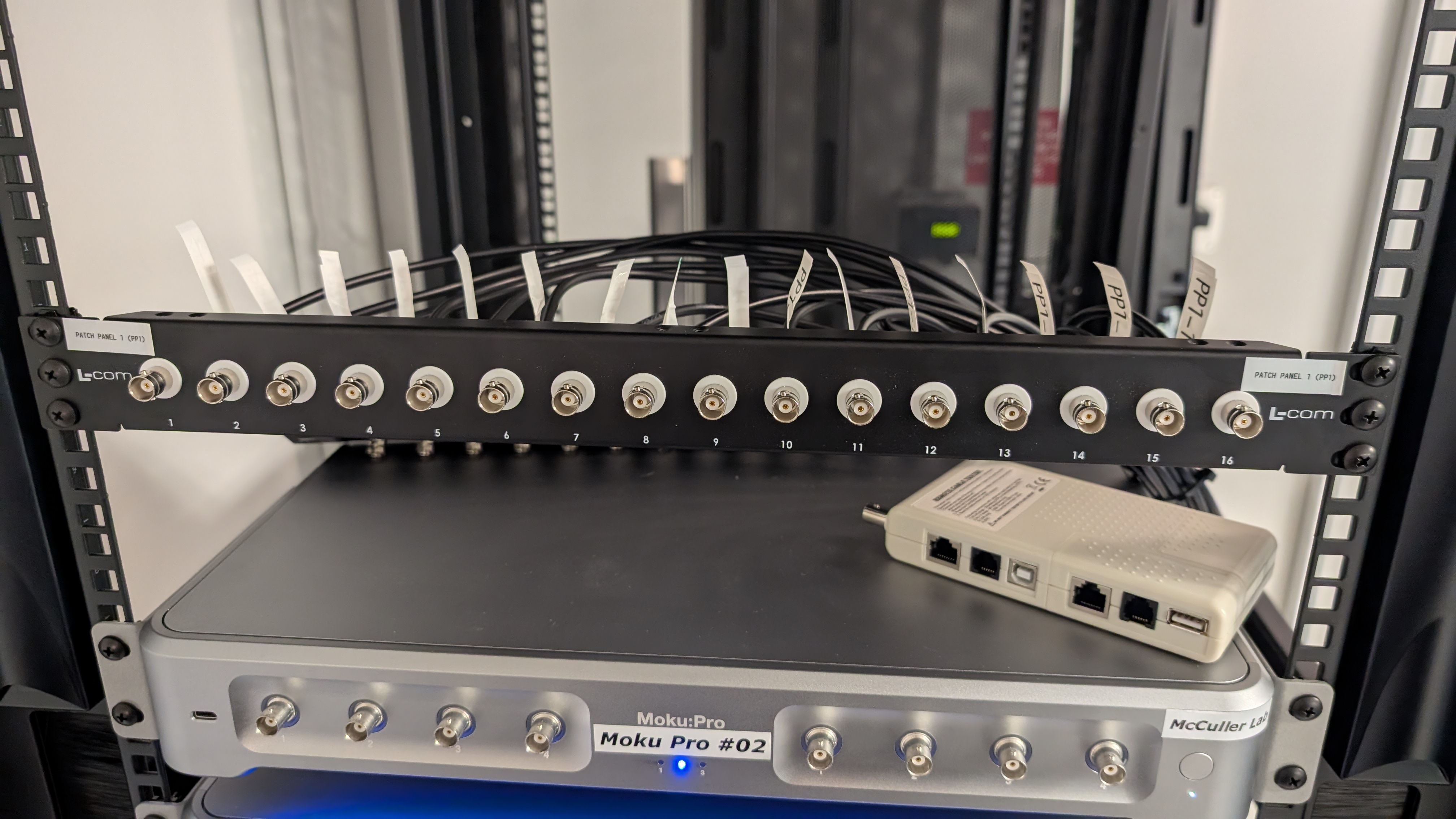
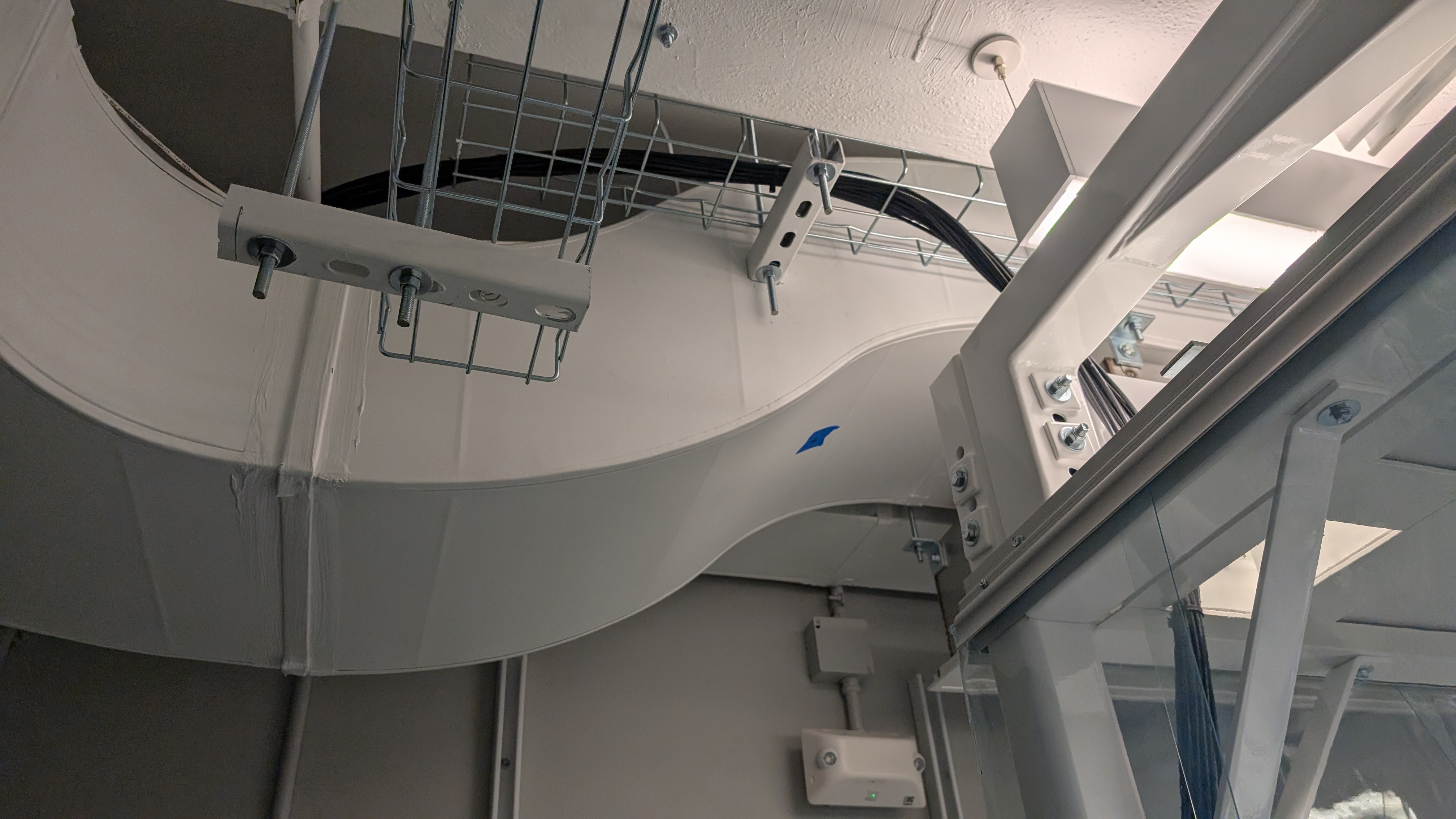
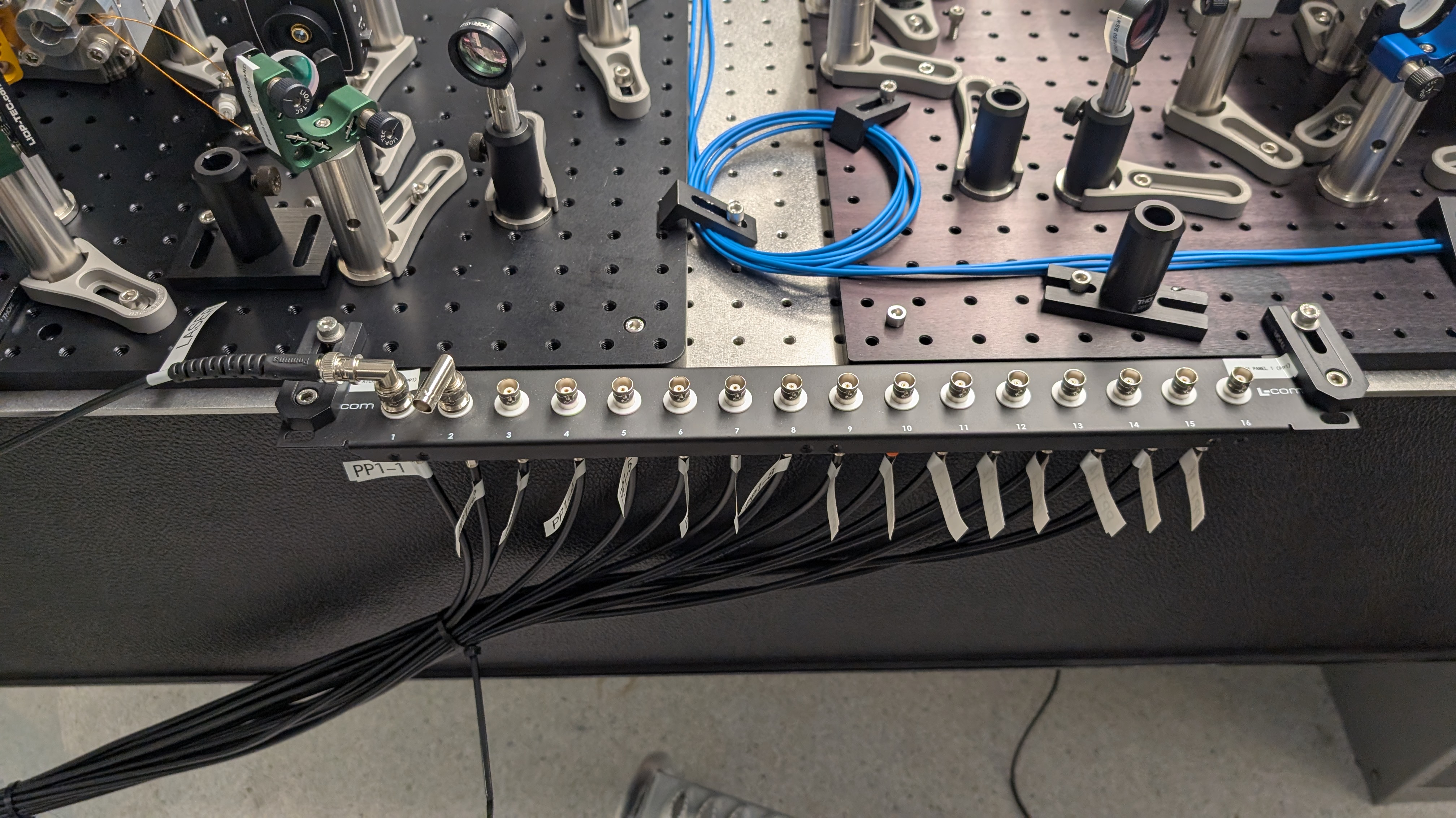
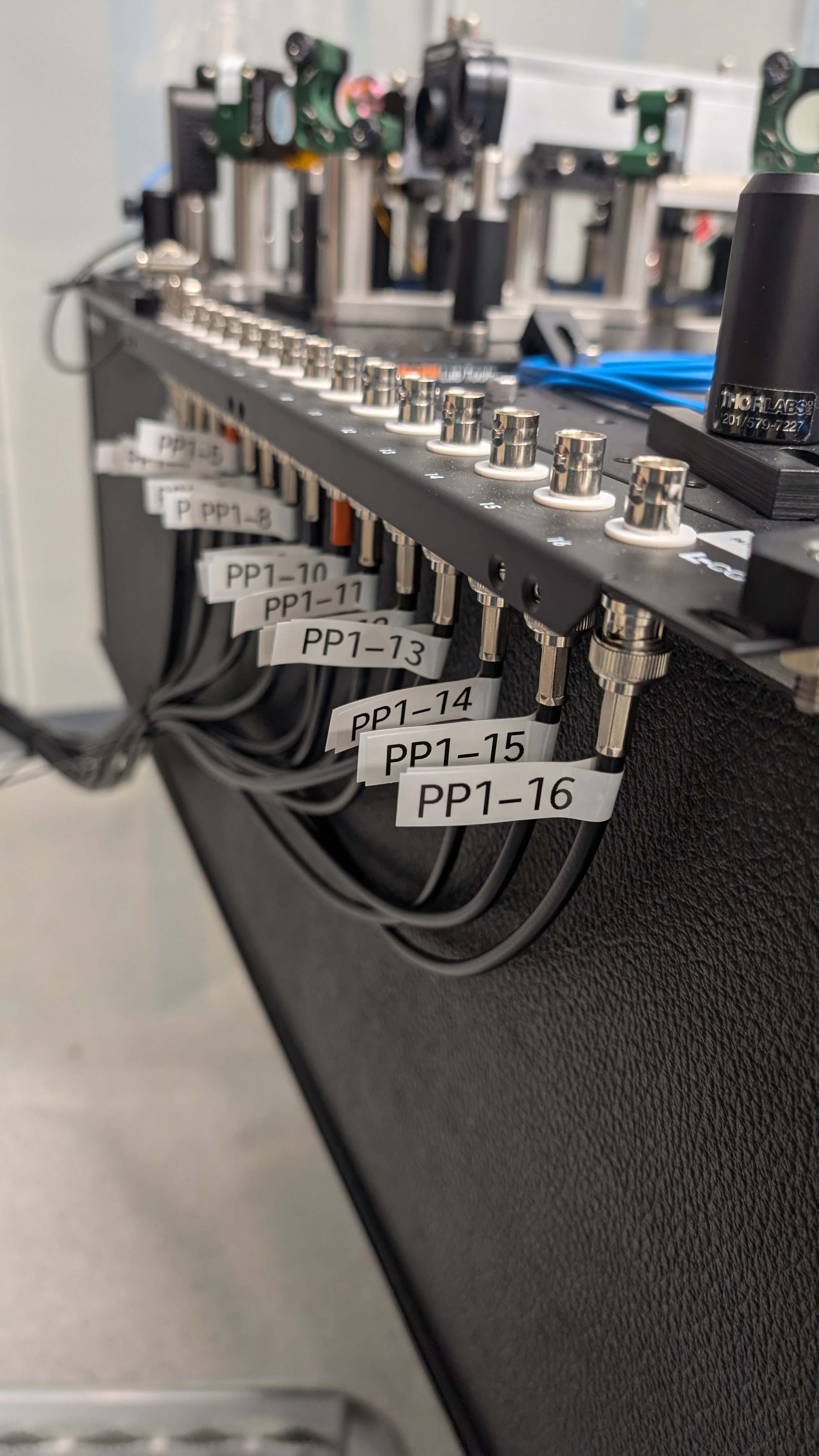
I cut a corner out of a tile (of unknown material) that goes in the mobile clean room using a bandsaw. This allows the patch panel cables to go from the optics table to the rack. The tile was easy to cut and didn't generate any dust.
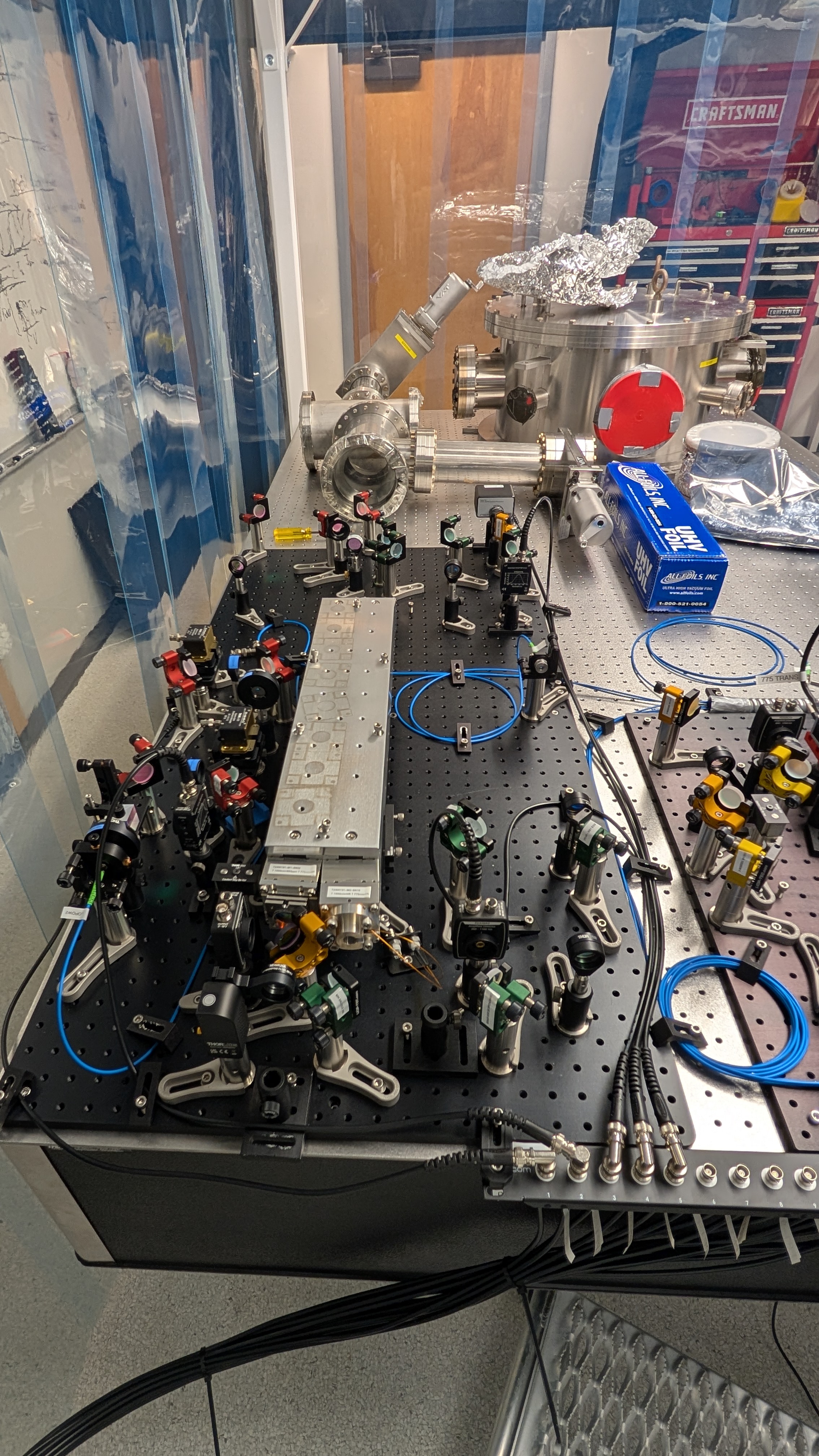
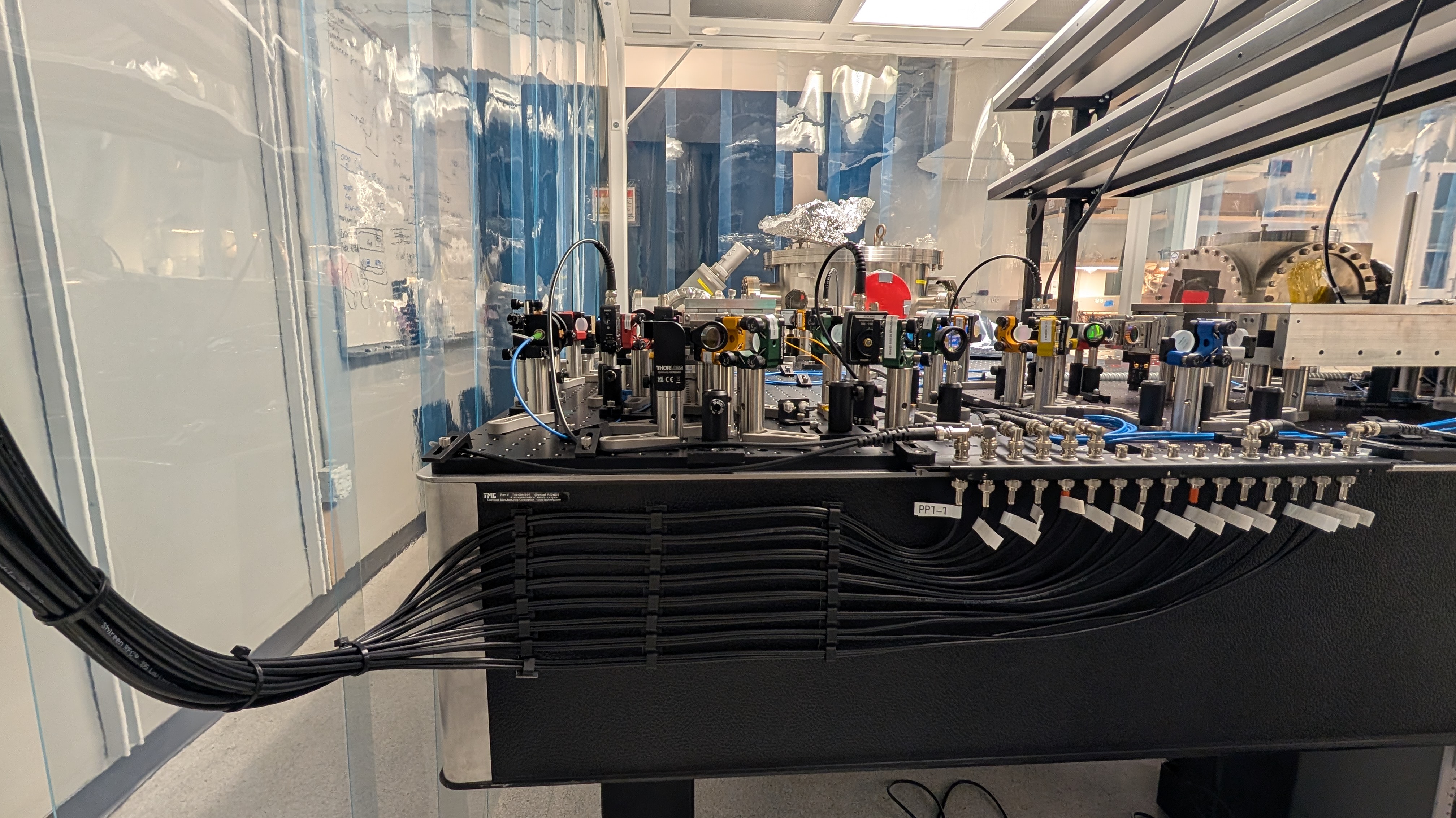

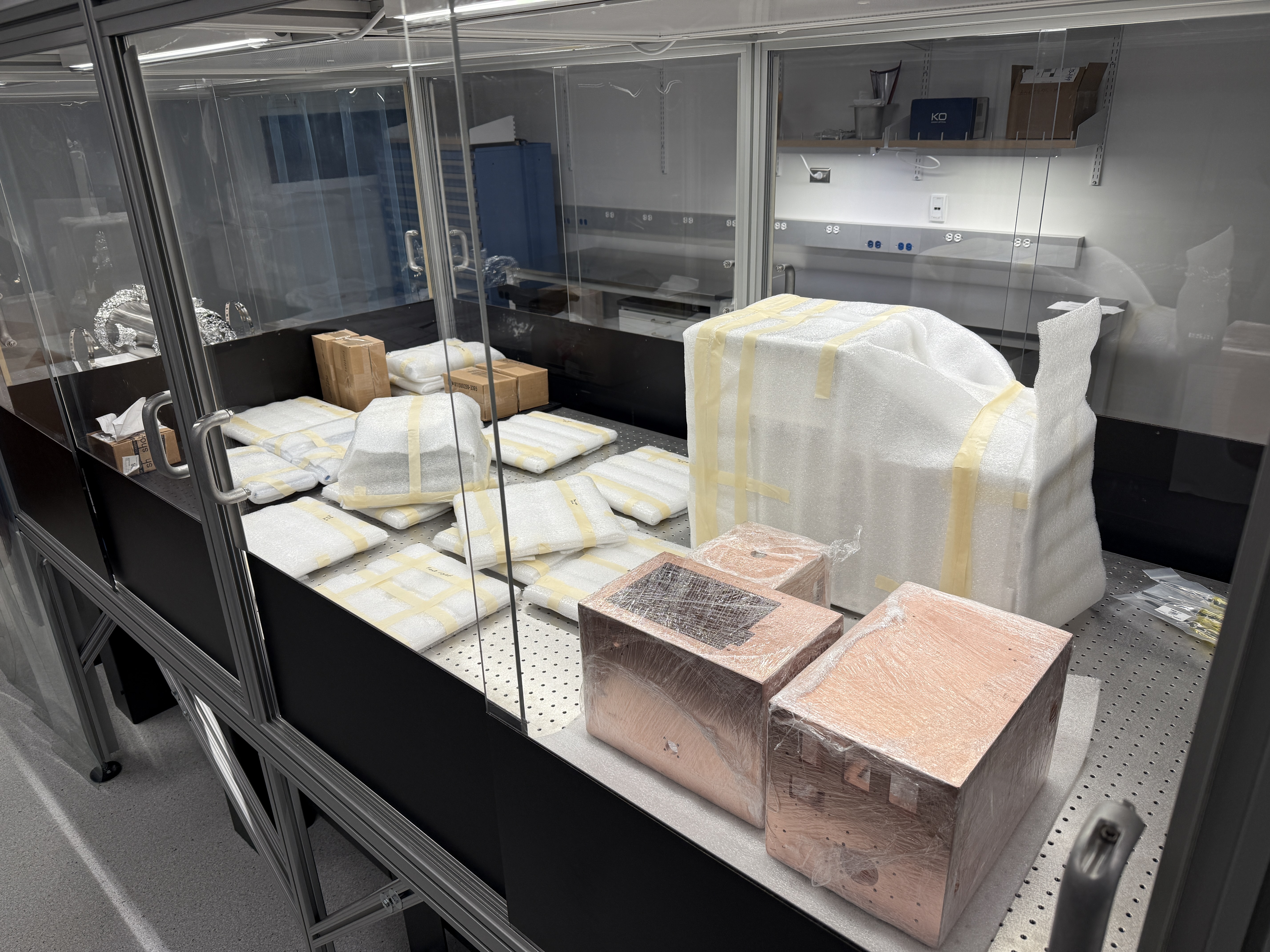


I did the same thing to a 2nd tile for a 2nd set of cables. To also allow for the passage of other cables, I made this cut a 2" by 2" square. I placed the tile back to prevent dust from getting into the clean room over the weekend (or longer).
I think they are just acrylic sheets.