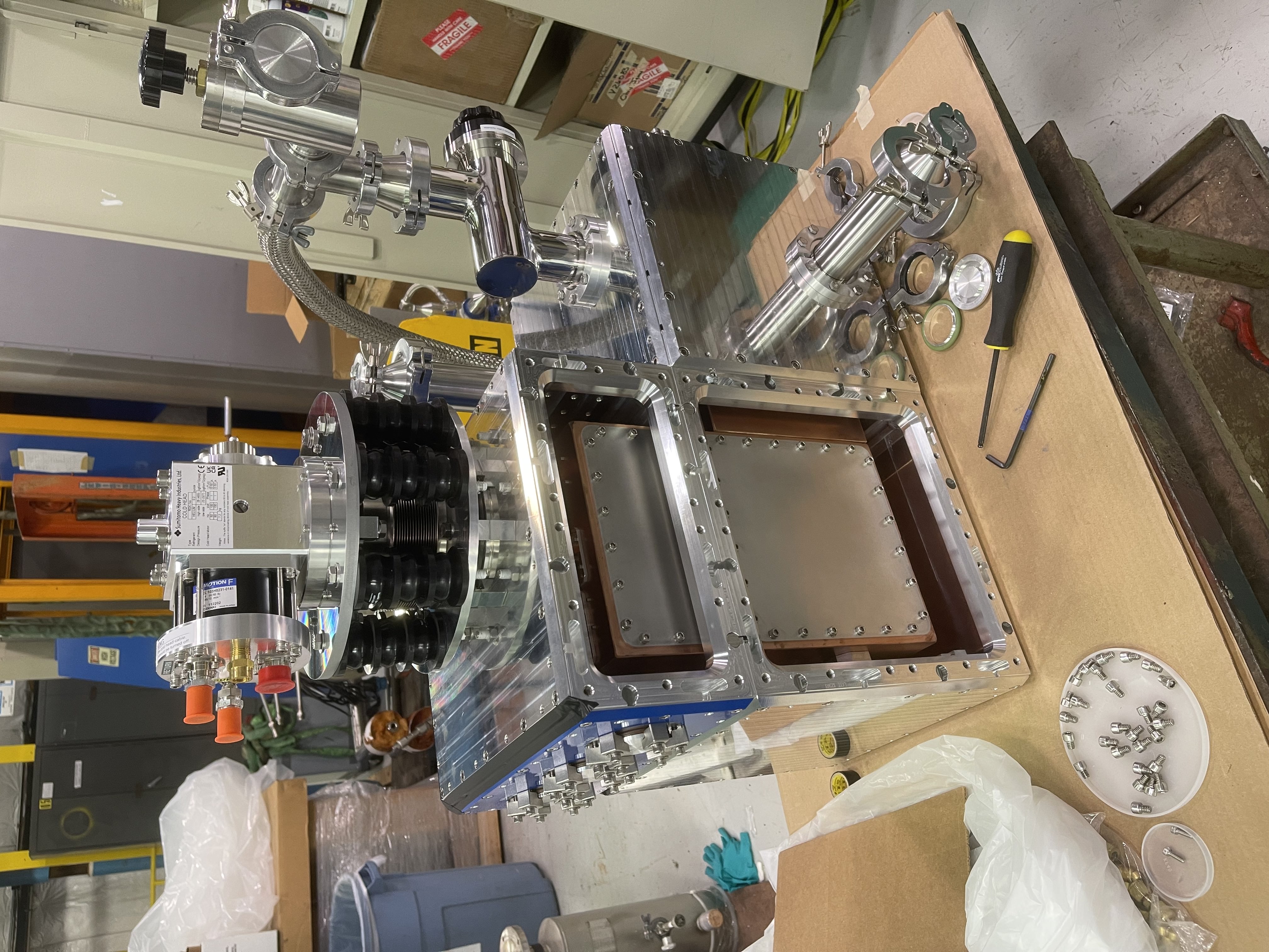
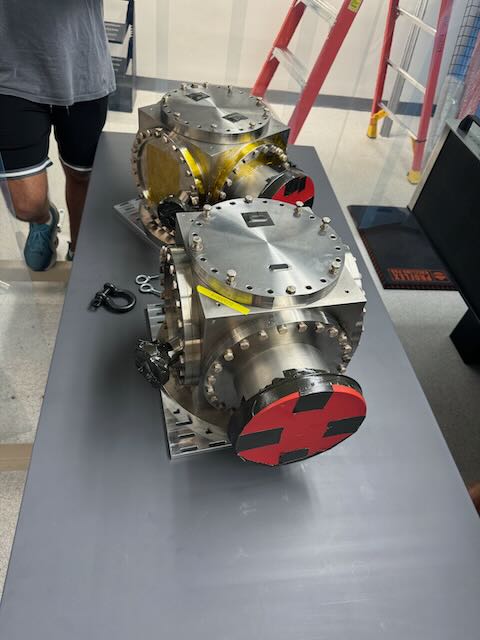
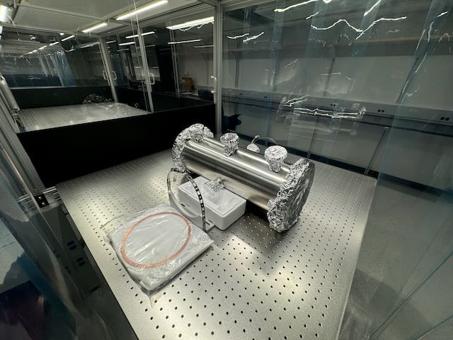
During my visit to FNAL, we have been working toward the goal of prepping the Dewar for final shipment to Caltech.
When I arrived the Dewar was assembled and pumped down (without greasing any O-rings) to a leak rate of 10^-4 or 5.
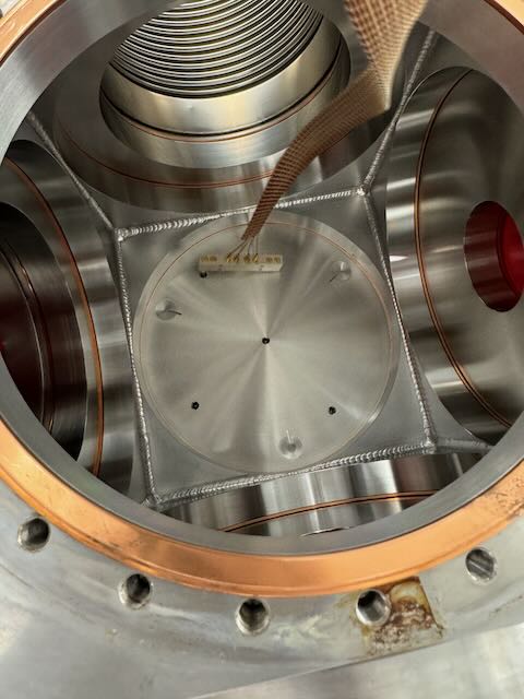
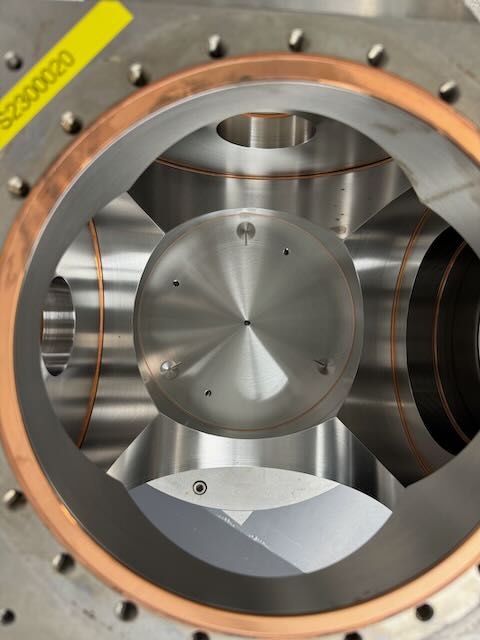
We then performed leak tests using helium and a helium detector to pinpoint a few locations for possible leaks.
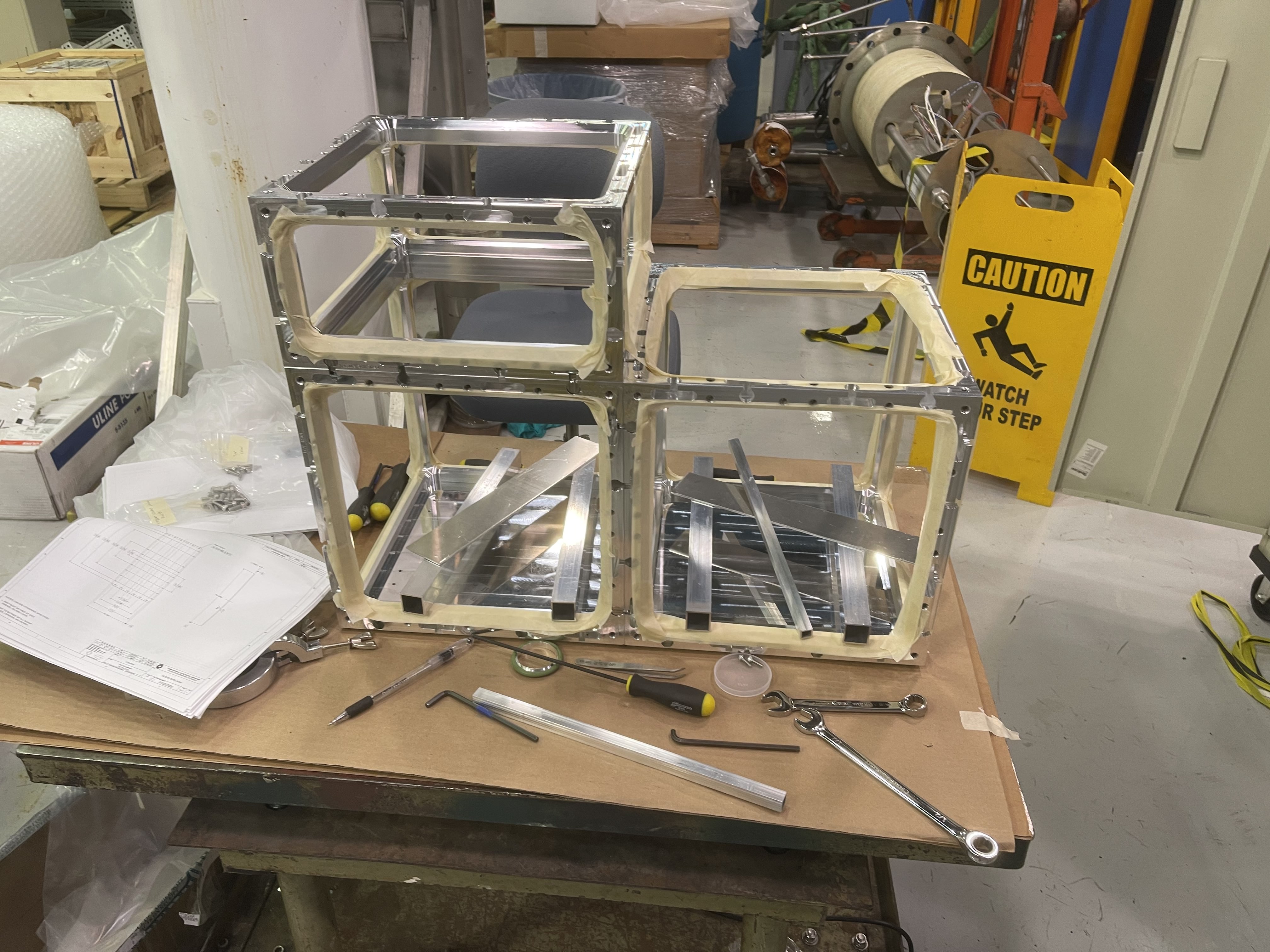
Upon dismantling the entire device, I could locate a few particles of dust, debris, and fibers that may have caused these leaks and warked areas of concern with possible micro scratches or abrasions to the sealing surface of one of the inner cubes. We expect that on the second test, bringing the Dewar to vacuum to leak check for Thursday and sealing with vacuum grease, we will see a majority of these leaks disappear. Great care and meticulous cleaning were done in preparation for this cycle, so we will post the results on our leak rate tomorrow.
Some other notes to take into consideration when I am to get back to Caltech:
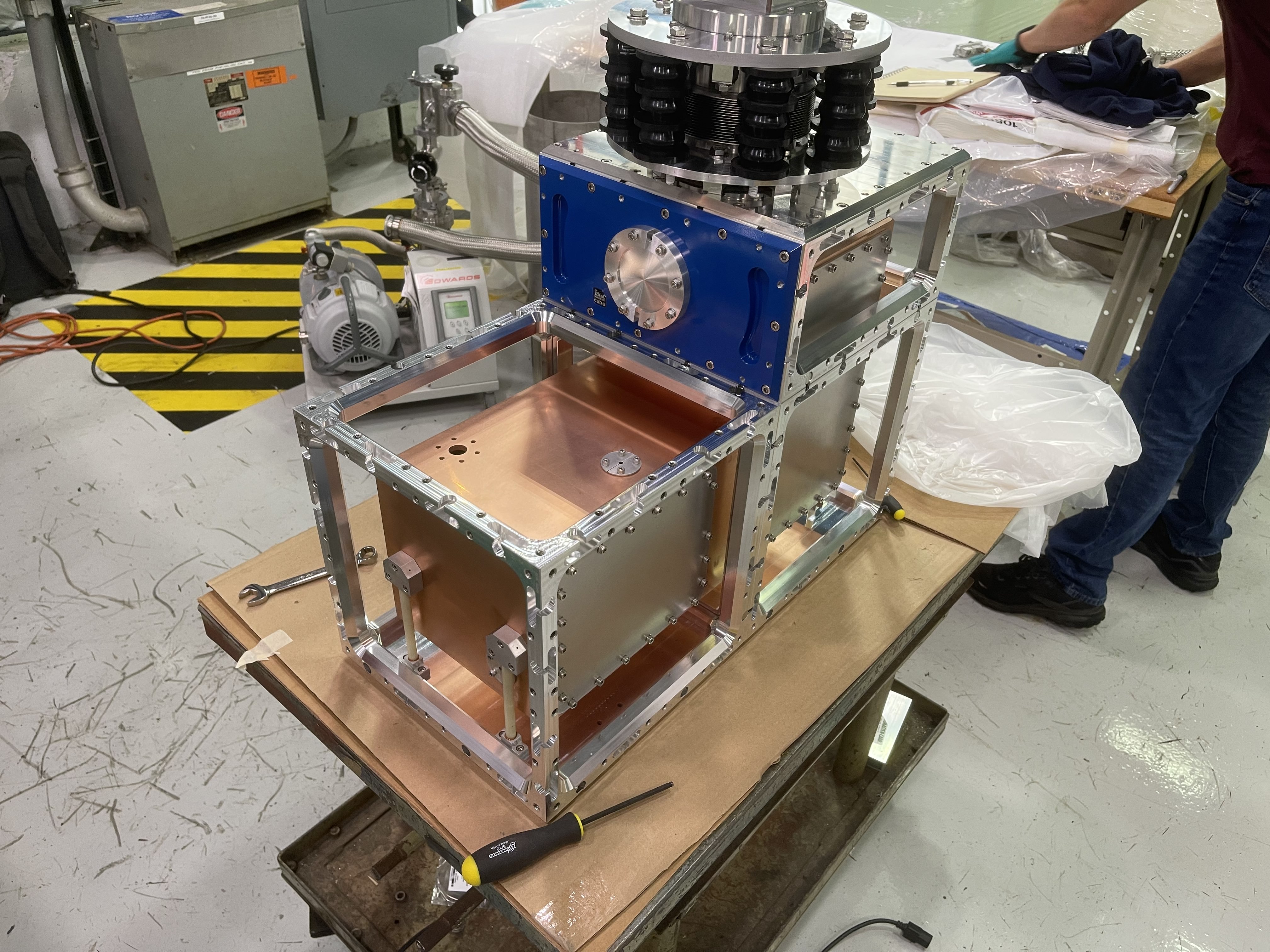
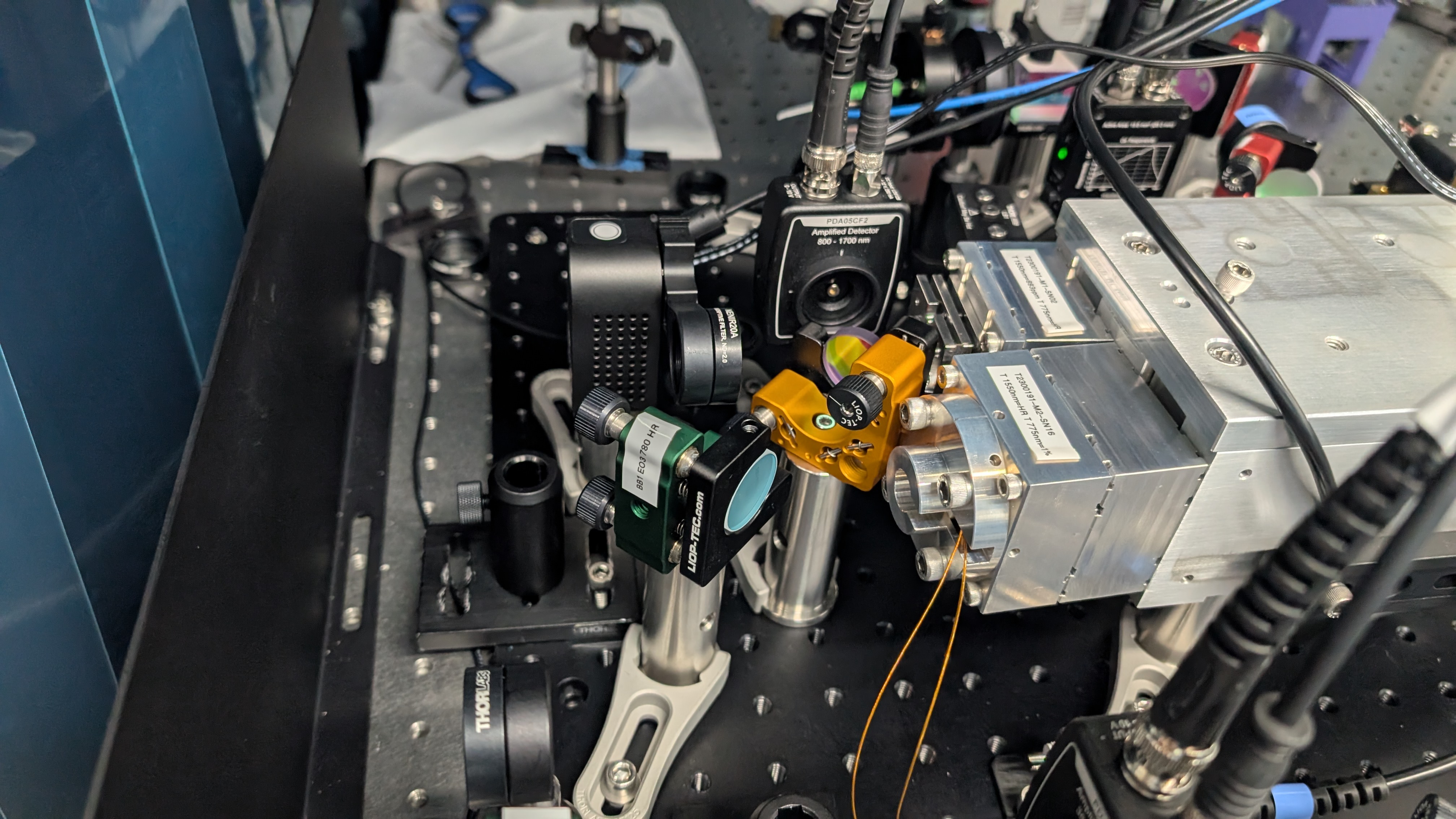
- The copper cube for the "free space" optics has 2 notes.
1. When manufacturing the plate for it, they were unable to meet the spec we initially required for the optics, thus each of the tapped holes is set to a tolerance of +-1 thousandth true position rather than 0.5 thousandths, this may or may not affect our alignments, but we will have to see when testing the dewar fully.
2. These holes were made blind, they are through holes and will need to be blocked underneath with plugs or taped over with copper tape to block the light out. If this is a huge issue and the tape is not cutting it, we can also send it to the manufacturer for them to weld seal the holes.
- All copper plates and components have been designed without helicoils as they would greatly affect the conduction inside the copper cubes. Thus we must take great caution when bolting anything together with the copper boxes to not strip any of the components!
- That being said, all thermal specs were done for bolts to have been tightened to 25 foot-lbs of force, we should buy some torque wrenches for the reassembly.
- The copper is being passivated such that it is less likely to rust and is more durable over time, but this may need to be done again in the future (5-8 minute citric acid bath and 250-300 degree bakeout and cool down for 18 hours)
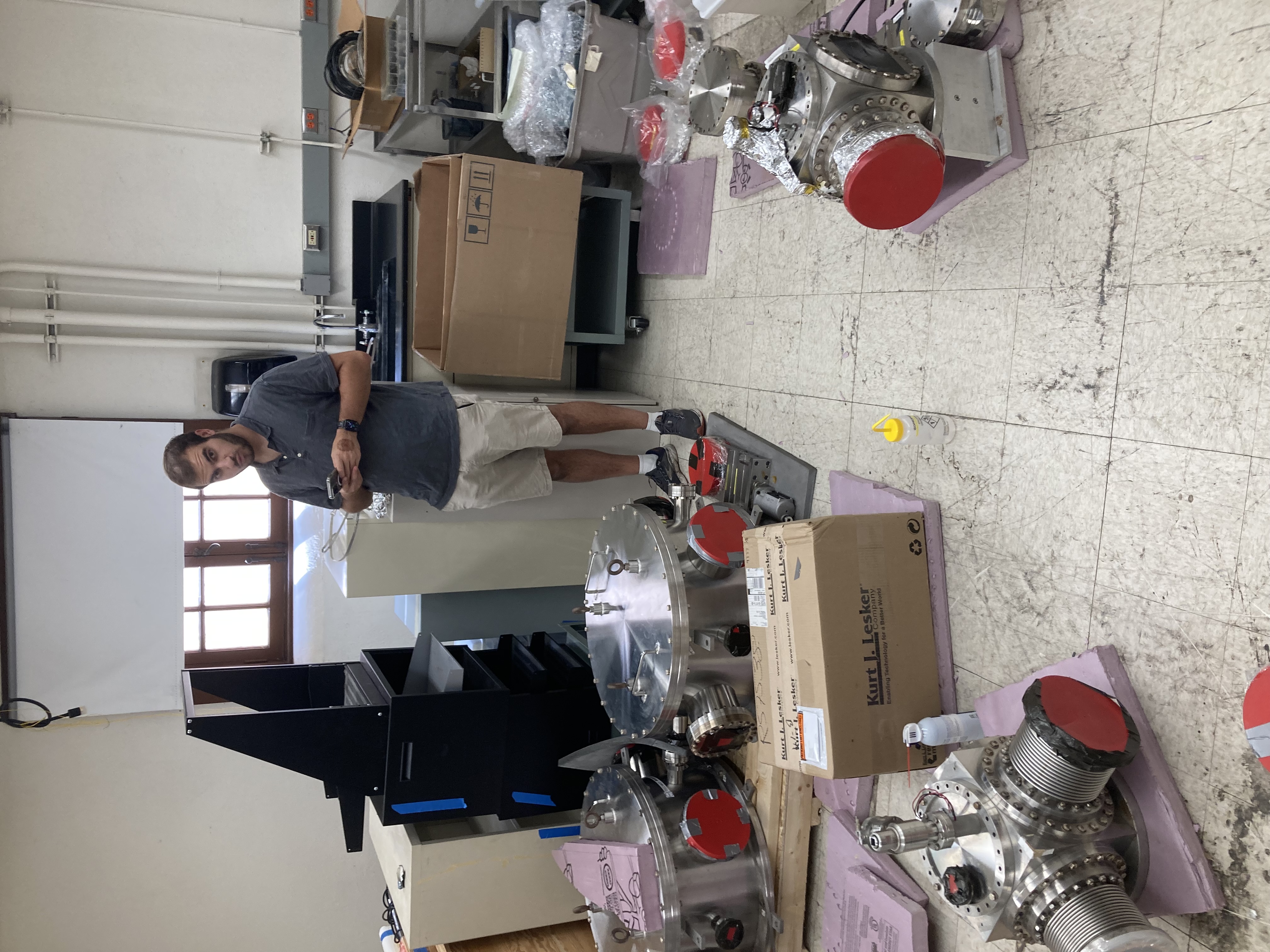
- A few of the boxes being shipped will have not been opened before, so we will need to do a full inspection of the components inside them to alert the manufacturers if anything is wrong or damaged from shipment.
- When the dewar is fully assembled it must not ever be tipped on its side as the G10 legs for the copper could be broken or damaged!
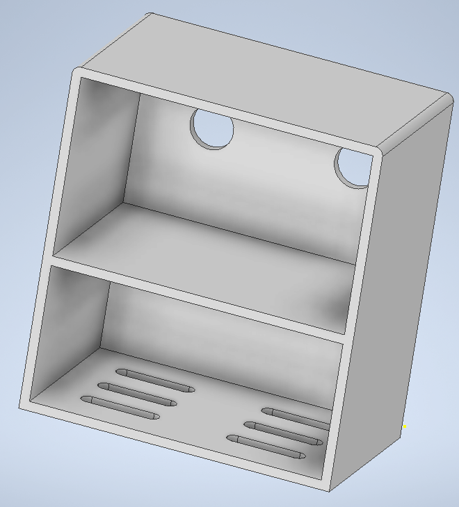
- Anytime we bring the dewar back to normal pressure (1 atm) we will want to infill with nitrogen, thus we will be adding a pressure relief valve to add a layer of safety when doing so and not overpressurizing the vessel.
Things to check up on with Boris and the SNSPD group regarding components for the Dewar:
- Did we order the XYZ stage? We will also need to do a bit of testing with its internal fine-threaded bolts and their susceptibility to expanding in low-temperature environments (may need to have them made out of aluminum or steel instead of brass)
- Have we ordered the feed-throughs for the XYZ stage aligning?
- Suggested we order an extra set of the G10 feet (erik@precisioncryo.com) - they will have our order info for a bit and could replicate our parts (Fermi PO# PO711633)