Displaying reports 41-60 of 1093.Go to page 1 2 3 4 5 6 7 8 9 10 End
Reports until 15:53, Friday 25 April 2025
Atoms General
Torrey Cullen - posted 15:53, Friday 25 April 2025 (12283)
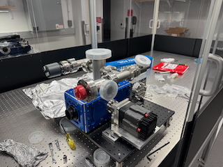
Rb Vapor Cell Start up

[Ian, Torrey]

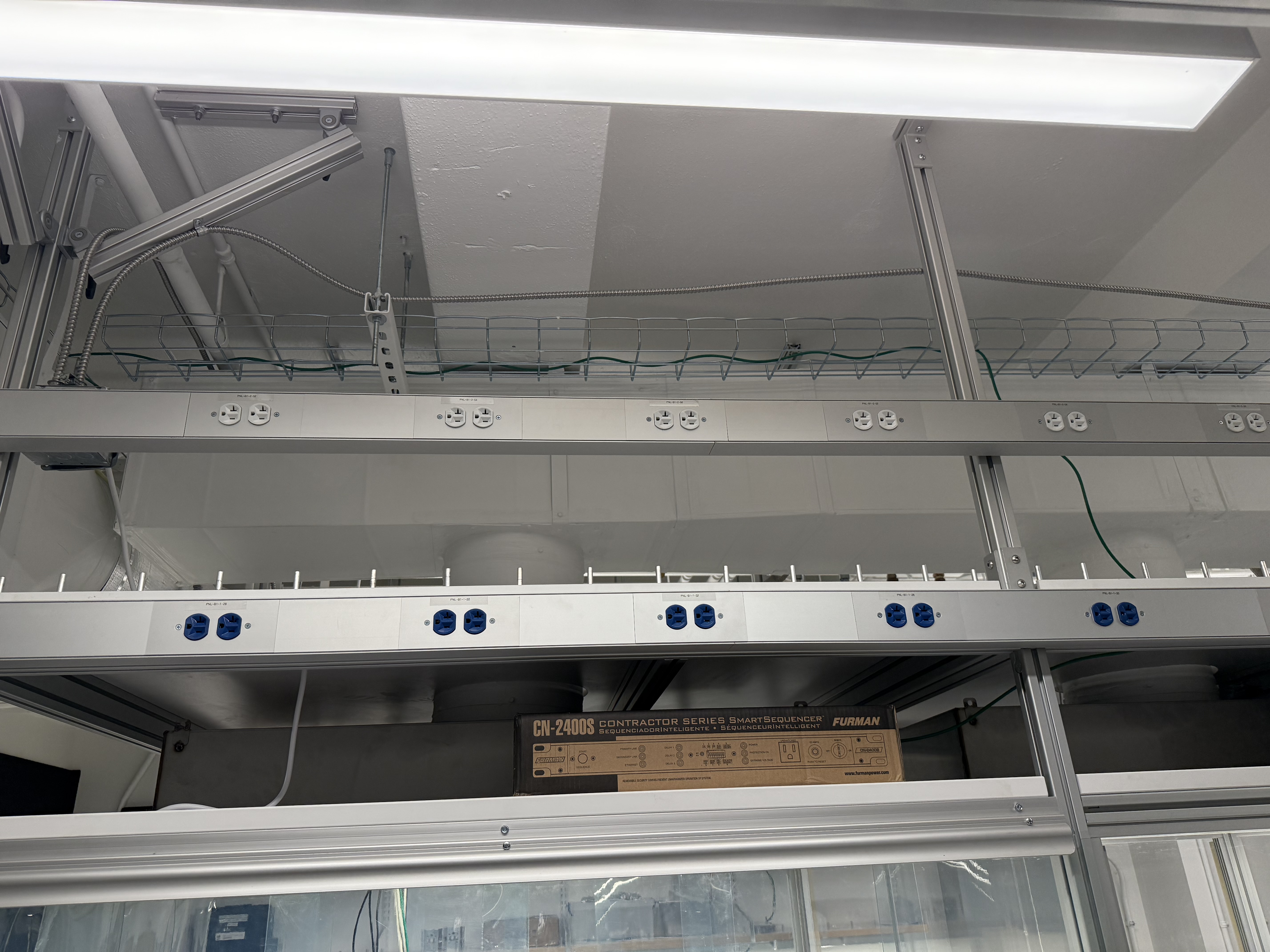
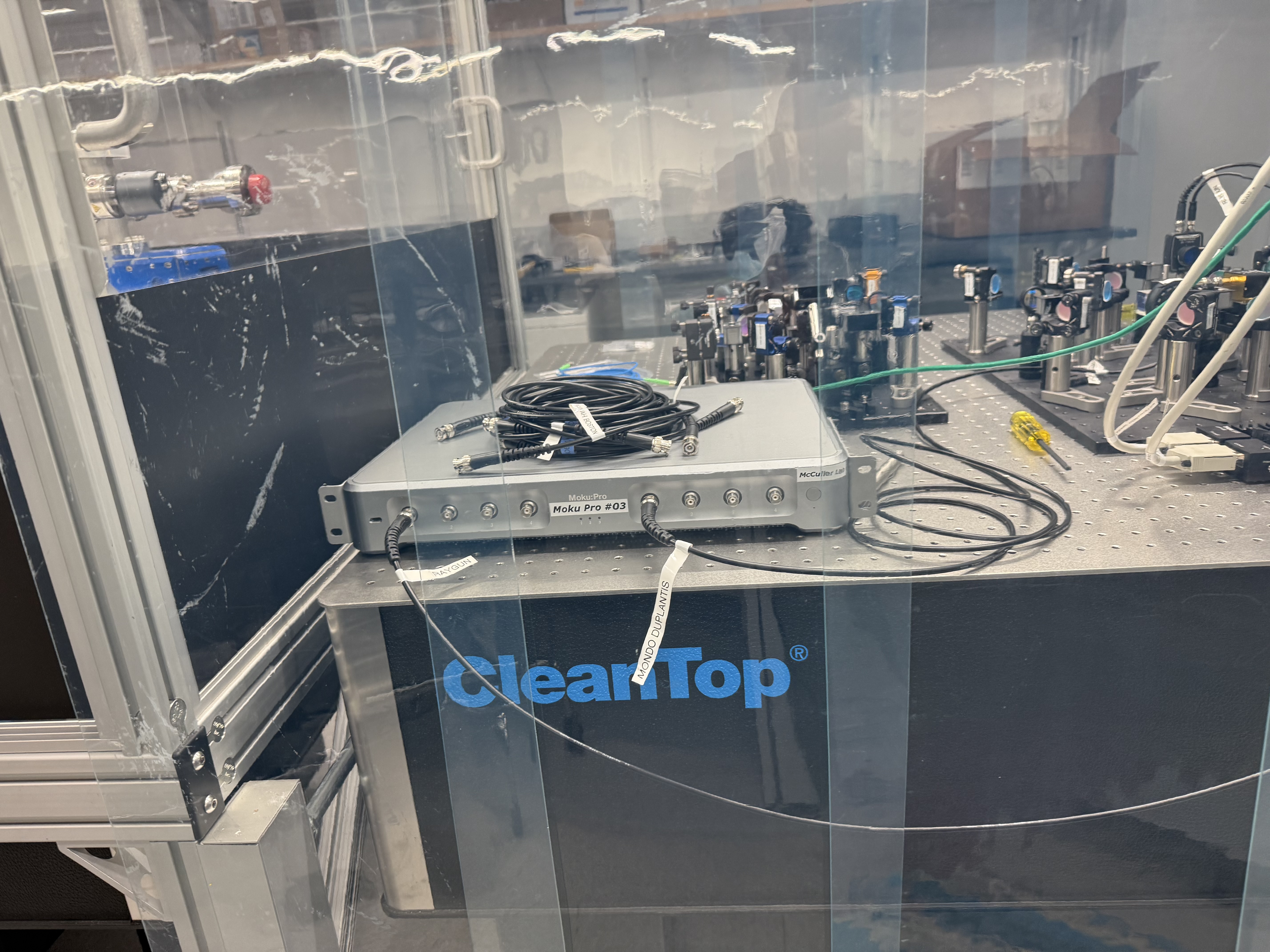
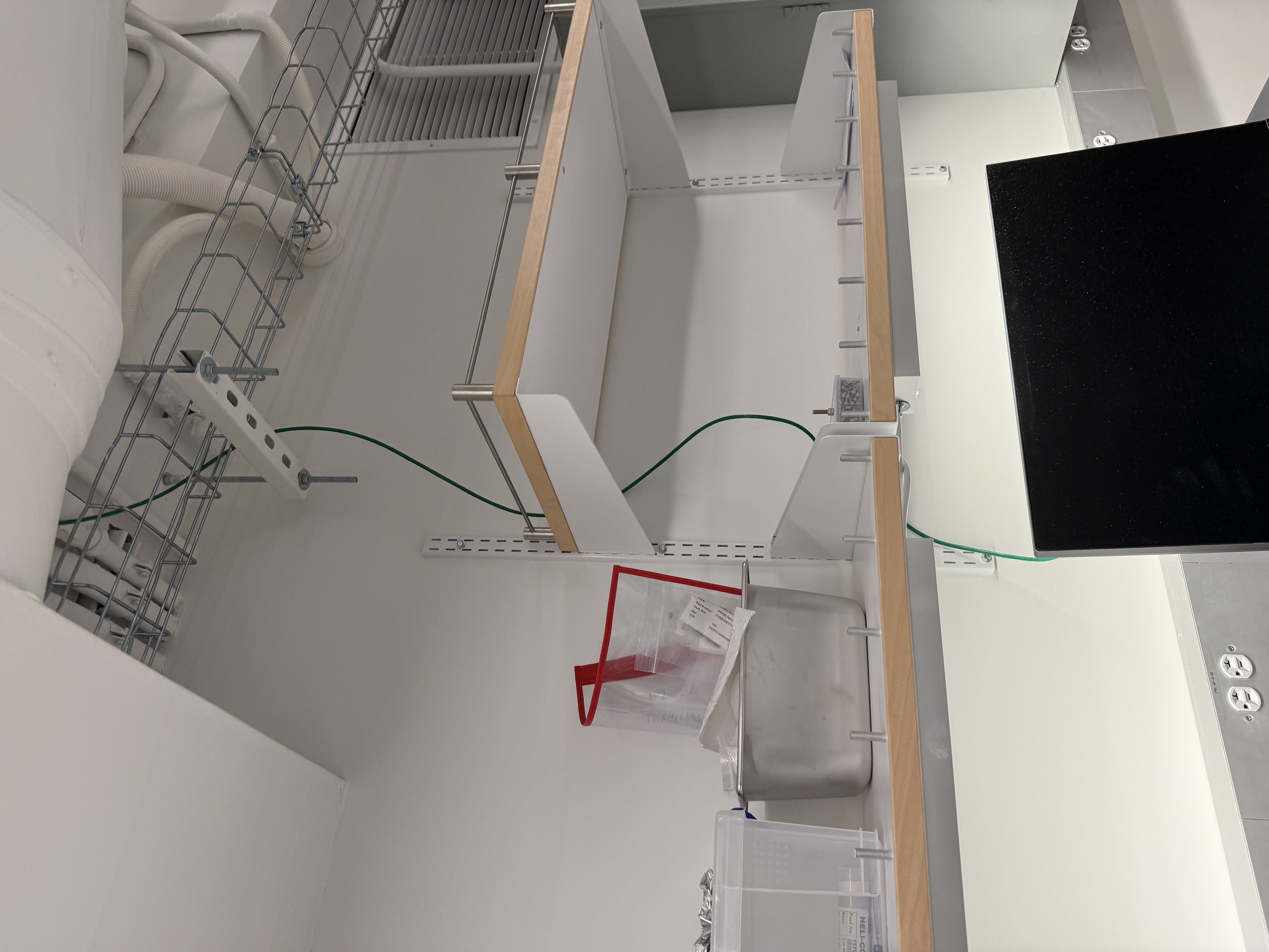
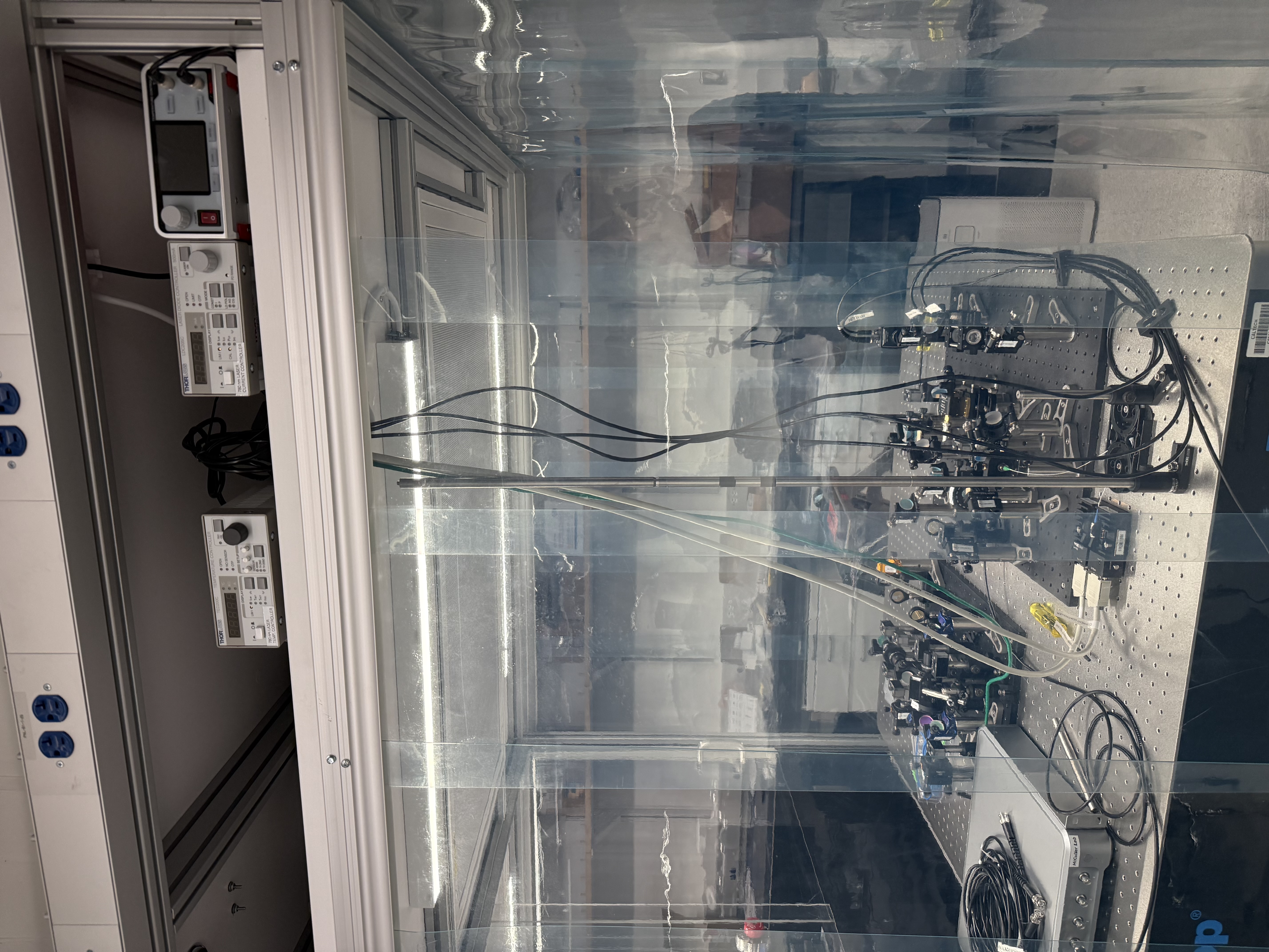
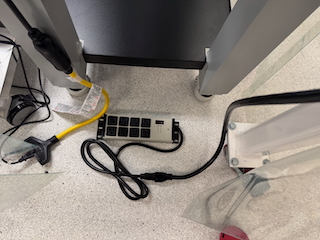
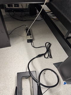
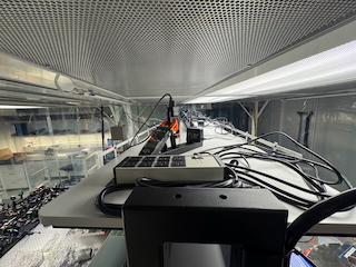
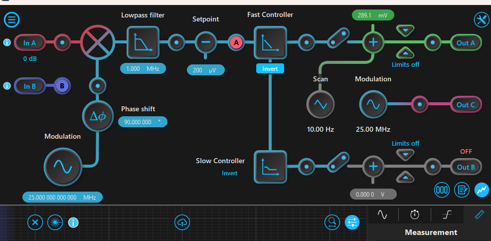
We want to start getting Briana's old set up going for the first time in B111A. We've started cabling and placing the required electronics. The 780 laser is now plugged in but remains off. We also wired the table  for ethernet, but we need an ethernet switch. I think we bought some but we cannot locate them. We also also placed a monitor and keyboard for where we'd like to have the associated work station, but a NUC or similar machine still needs to be purchased.

Images attached to this report
Vacuum Systems General (GQuEST)
Daniel Grass - posted 00:10, Friday 25 April 2025 (12282)
6 in to 4.5 in CF Reducer Flange Placed on top of IFO Cube

I placed a 6" to 4.5" CF Zero Length Reducer Flange on top of the IFO Cube for the Agilent TwisTorr 74 Turbo Pump (to be ordered). I tightened the bolts to 34 Nm and there was flange to flange contact all around. I also moved a Holometer part that held up an end cube for the elevated IFO into B105 since I don't think we will ever need it and it's quite dirty.

Lab Infrastructure General
Daniel Grass - posted 22:59, Thursday 24 April 2025 - last comment - 20:38, Friday 25 April 2025(12280)
1/4 in NPT Female to 1/4 in Barbed Female Converter Attached to N2 nozzles in lab

I added three 1/4" NPT Female to 1/4" Barbed Female Converters to the N2 nozzles in the B110 fume hood, West of the North clean rooms in B111A, and North of the mobile clean rooms in B111B. The 1/4" barbed female end should fit the 1/4" ID tubing I previously bought to back fill the LFC and RbQ Vacuum Chamber. We might need to split the nozzle off in B111A for our multiple vacuum chambers. To tighten the converter, I used a 9/16" and 17 mm wrench. I didn't crank it too hard. In the B110 fume hood, the air velocity is much higher now, which should allow for better solvent removal.

Comments related to this report
Daniel Grass - 20:38, Friday 25 April 2025 (12284)

[Ian, Daniel]

We attached a 1/4" ID hose from the N2 nozzle in B111B to the LFC up-to-air valve. We put it through one of the inner gaps for cables/cubes in the mobile clean rooms. We purged the tube with N2 briefly before attaching it to the LFC. We used hose clamps to attach the hose; the hose clamp on the barbed nozzle was not particularly helpful as the hose is pretty secure without it.

Vacuum Systems General (RbQ)
Daniel Grass - posted 22:52, Thursday 24 April 2025 - last comment - 22:52, Thursday 24 April 2025(12276)
Angle Valves, Up to Air Valve, and Pressure Gauge Attached to RbQ Vacuum Chamber

[Jeff, Daniel]

We attached the 2.75" CF Angle Valve, the 2.75" All Metal Angle Valve (angled so that the Residual Gas Analyzer fits), the up-to-air valve, and the Agilent FRG702 pressure gauge to the RbQ Vacuum Chamber. None of the bolts are tightened. So that the magnet doesn't move, we used 1.25" long 1/4-28 bolts to attach the pressure gauge. Hopefully this works well.

Images attached to this report
Comments related to this report
Daniel Grass - 22:50, Thursday 24 April 2025 (12279)

I tightened all the bolts until there was flange to flange contact around the whole connection. The 1.25" long bolts did fine, but I still think longer bolts are generally advisable to avoid stripping a thread.

Images attached to this comment
Electronics General (GQuEST)
Daniel Grass - posted 22:48, Thursday 24 April 2025 - last comment - 20:40, Friday 25 April 2025(12278)
NEMA L5-20P to 5-15/20R Extension Cords and Heavy Duty Power Strips Placed in B111B Mobile Clean Rooms

I placed two NEMA L5-20P to 5-15/20R Extension Cords on the "dirty" power outlets and placed 3 Heavy Duty Power Strips in B111B Mobile Clean Rooms. My idea is these "beefy" power strips indicate they're for things that don't need clean power, like pumps. I haven't hooked up the pumps to them yet as they're in use, except the LFC Scroll Pump which was and is turned off. See attached photos for their locations: the Northeast corner of the clean rooms, underneath the insersection of the optics tables, and on the top shelf.

Images attached to this report
Comments related to this report
Daniel Grass - 20:40, Friday 25 April 2025 (12285)

After Alex turned off the pumps and fully vented the SNSPD Dewer, I disconnected the pumps and connected them to the heavy duty power strip. I removed the NEMA L5-20 Extension cord that was previously used that didn't reach to the ground and put it away on the south shelves with the other cords.

GQuEST Output Filter Cavities
Torrey Cullen - posted 11:38, Thursday 24 April 2025 (12277)
Moku Clock Sync

Stumbled upon a minor find. It seems syncing the moku clocks is enough to allow simultaneous demodulation of the 25 MHz phase modulation on the 775 light without referencing the signal.

EX: Sync moku clock via reference output on the back. Put 25 MHz 2V pp + 14 dB signal on Moku 4 output 3, going to EOM. Attempt to lock the other cavity, on a different moku, with no phase modulation signal output (laserlockbox.png, it thinks its making a 25 MHz signal, but the clocks are synced well enough to demod the other signal). Have to adjust the phase slightly but otherwise this just works. Prevents us from having to split this signal and feed it into each moku and then reference as external. Maybe this is obvious to others but I was suprised this worked. You get a slightly larger error signal peak to peak amplitude if the signal is coming from the moku you are using, but a small one (~8% increase).

Images attached to this report
Vacuum Systems General (GQuEST)
Daniel Grass - posted 00:33, Thursday 24 April 2025 - last comment - 22:59, Thursday 24 April 2025(12275)
2.75 in CF Tee, Composite Angle Valve, and 6 in CF Gate Valve Attached to IFO Cube

[Jeff, Daniel]

I attached a 2.75" CF Tee to the West side of the IFO Cube and tightened the bolts. I then attached a 2.75" CF composite angle valve on the North side of the Tee. This is meant for the leak checker. I haven't tightened the bolts.

Jeff and I then added a 6" CF Gate Valve to the top of the 6 way cross. I haven't tightened the bolts. This is meant for the turbo pump. All parts were disassembled from the Holometer parts.

Comments related to this report
Daniel Grass - 22:59, Thursday 24 April 2025 (12281)

I tightened all the bolts.

Vacuum Systems General (GQuEST)
Daniel Grass - posted 01:38, Wednesday 23 April 2025 (12272)
2.75 in CF Parts from Holometer Disassembled; up-to-air valve attached to IFO Cube

I attached the up-to-air-valve to the IFO Cube and tightened the screws fully to flange to flange contact. I then disassembled a bunch of 2.75" CF Holometer Equipment, including a tee, a 4 way cross, and an angle valve. I will later disconnect an elbow and cheap pressure gauge (down to 1 mTorr).

Vacuum Systems General (RbQ)
Daniel Grass - posted 19:56, Tuesday 22 April 2025 (12271)
Infleqtion Cold Rb PICAS Assembled and Installed on RbQ Vacuum System; 2.75 in CF Tee also installed

[Jeff, Daniel]

We finished tightening the bolts on the 1.33" CF flange from the Rb vapor cell to the adaptor plate using the 9/64" stubby (low profile) hex key. We then installed the alignment plate to the adaptor plate, the adaptor plate to the the coils sub assembly and the laser sub assembly, tightening the bolts at each step. 

We then attached the bellows (one end is already attached to the adaptor plate) to the 2.75" CF flange on the Ideal Vac Chamber. We used the molded piton gasket, which worked very well at keeping in place. We also used the custom plates I made for support and alignment. I should have made the hole larger than 2.76" to account for the plate nuts sticking out past the flange. Although tightening the bottom screw was particularly challenging, we tightened the screws so that the flange made contact with the Ideal Vac Plate.

We then installed a 2.75" CF Tee to the 4.5" CF to 2.75" CF reducing 4 way cross and tightened the bolts fully

Environmental Seismic
Ian MacMillan - posted 17:00, Tuesday 22 April 2025 (12268)
Seismic Sensor Installation

I installed the Wilcoxon 731A seismic accelerometer and its associated P31 power supply. On the table near the filter cavities shown in the close up image of the seismic accelerometer. I hooked it up to the patch panel to port red 8. I then hooked it up to a moku pro to test it. It seems to be working and I tested it by jumping next to it. I have not calibrated the data coming out of it yet.

I moved the case to a shelf in the RbQ lab. See Seismic_Accelerometer_Case.jpeg for location.

Images attached to this report
GQuEST Output Filter Cavities
Torrey Cullen - posted 16:52, Tuesday 22 April 2025 (12267)
Uploading experimentally taken transfer function as an inverted filter on the moku - continued

[Ian, Torrey]

Continuation of 12256.

Testing the script in action. I rewired the set up to mimic how this data was taken and reconfigured moku 1. This includes VCO locking cavity 1 and having the FRA output going to the piezo. Take the updated data, run it through the code, upload to moku, and track performance with the uploaded filter on and off.

Between nofilter.png, the customfilter.png, and customfilterincreasedgain.png (increasing the single leading value in the text file to 3, from 1), reduces the overall RMS from 650 uV -> 550 uV -> 416 uV. Note that you cannot increase the gain arbitrarily high as it will cause piezo to ring up if too high (was too high at 5). This seems successful, but we still need better control overall.

Images attached to this report
GQuEST Output Filter Cavities
Torrey Cullen - posted 11:57, Tuesday 22 April 2025 - last comment - 12:15, Tuesday 22 April 2025(12265)
OFC3 Alignment complete

OFC3 1550 alignment is complete. To recap, the 1550 OFC3 path has no test light. It is aligned directly to the output of OFC2. In order to achieve this we built a 1550 PDH scheme for OFC2 for more stable locking. I can then scan on the piezo in OFC3 to find cavity flashes. Additionally I had to implement some periscoping mirrors as outlined in previous posts.

One problem: OFC3.png is a cavity scan. In red is the PDH error signal for the 775 light and in blue is the 1550 TRANS signal. Fairly clean cavity scan. There seems to be a large unexplained frequency drift, as seen in ScreenRecording2025-04-22114505.mp4. This drift is significant portion of the cavity FSR (10's of MHz) and appears to just be the cavity/piezo. I don't believe it is the laser, as you can track the correction voltage being applied to the DC Modulation port of the teraxion via its interface teraxion.png. May be worth recording this data and making sure but quick look by eye it doesn't seem to be the case. Additional proof for this not being the laser is the fact the 775 and 1550 drift the same amount. If it was the laser the 775 light would be moving twice as fast due to the SHG frequency doubling.

Images attached to this report
Non-image files attached to this report
Comments related to this report
Torrey Cullen - 12:15, Tuesday 22 April 2025 (12266)

After talking with Sander I think these may make sense. These are bigger than the normal fluctuations seen in the other cavities, but there are still some in the other cavities. The explanation being, the first cavity has some mechanical fluctuations that the laser has to track. Since we lock the first cavity to the laser, those fluctuations are imprinted on the laser light that is exiting the first cavity. Then the new cavity has its own fluctuations PLUS the first cavity fluctuations to track with the piezo. I think this explains the larger fluctuations in the new cavity.

Vacuum Systems General (GQuEST)
Daniel Grass - posted 01:49, Tuesday 22 April 2025 - last comment - 19:33, Tuesday 22 April 2025(12264)
Three 6 in CF to 2.75 in CF Zero Length Reducer Flanges Installed on IFO Cube

[Jeff, Daniel]

We installed three 6" CF to 2.75" CF Zero Length Reducer Flanges on the 6" CF 6 way cross (horizontally except the south side). I tightened the west flange all the way to 34 Nm with full flange to flange contact. I tightened the north and east flange to 34 Nm but only a few turns at 34 Nm.

Comments related to this report
Daniel Grass - 19:33, Tuesday 22 April 2025 (12270)

I tightened the remaining 2 flanges to steel to steel contact at 34 Nm.

Equipment Loans (GQuEST, RbQ)
Daniel Grass - posted 20:49, Monday 21 April 2025 (12263)
#8-32 Tangless Helicoils, Insertion and Removal Tool Borrowed

I borrowed the #8-32 Tangless Helicoil Insertion and Removal Tools from Stephen Appert. I also "borrowed" some Nitronic 60 #8-32 Length = Diameter Helicoils (it's going to be hard to return them once we use them). It's been logged here by Caltech LIGO Lab. I previously borrowed some #2-56 helicoils and tools and some #1/4-20 helicoils and tools. Everything is in B111A except the 1/4-20 helicoils, which are temporarily in B110 since I cleaned some of them.

GQuEST Output Filter Cavities
Torrey Cullen - posted 16:51, Monday 21 April 2025 - last comment - 14:59, Wednesday 23 April 2025(12256)
Uploading experimentally taken transfer function as an inverted filter on the moku

[Ian,Torrey]

In order to more stably lock the filter cavities, we have been in talks of taking cavity transfer functions to isolate any resonances to upload an invert version of the TF as a filter in the DFB. We have written a script to make this work. Here are the following steps:

1) Take OFC TF. rawdata.png

2) Rescale the magnitude of the data so that it is 0 at low frequencies.

3) Invert it in complex form and choose the appropriate window for the filter. invertedandwindowed.png

4) Down sample the data to make the experimentally taken data smoother.

5) Fit the down sampled data to ZPK format. ZPKfit.png

6) Convert your ZPK curve into second order sections.

7) Write it to a text file in the format the moku wants. output.txt

success.png (I moved it down 20 dB so you can see the shape at high frequencies. This is done with the leading single digit on its own line in the text file.)

Some notes associated with this:

-The moku can only upload 4 SOS in this format as a custom filter. Limits the amount of shape we can add to our filter dramatically.

-We will upload this script to the log in a cleaner format but for now here it is piezoTF_calculation.ipynb. Its really messy though, we'll update with a cleaner version soon. 

Images attached to this report
Non-image files attached to this report
Comments related to this report
Torrey Cullen - 13:40, Wednesday 23 April 2025 (12273)

Here is a cleaner version of the same script.

Non-image files attached to this comment
Torrey Cullen - 14:59, Wednesday 23 April 2025 (12274)

Data for the script.

Non-image files attached to this comment
Displaying reports 41-60 of 1093.Go to page 1 2 3 4 5 6 7 8 9 10 End