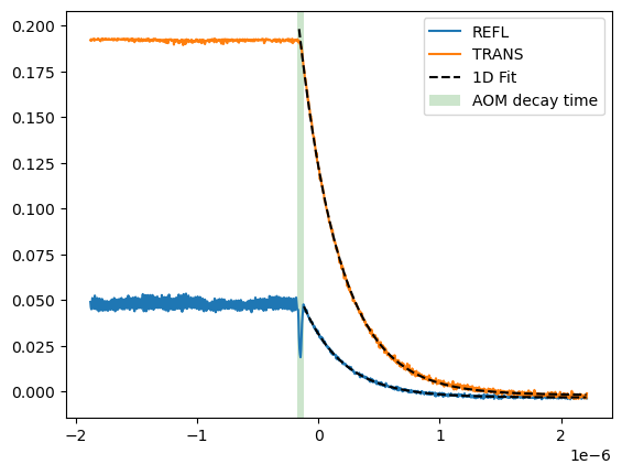
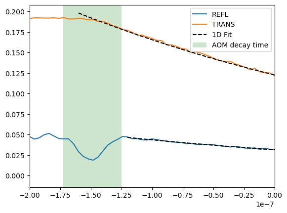
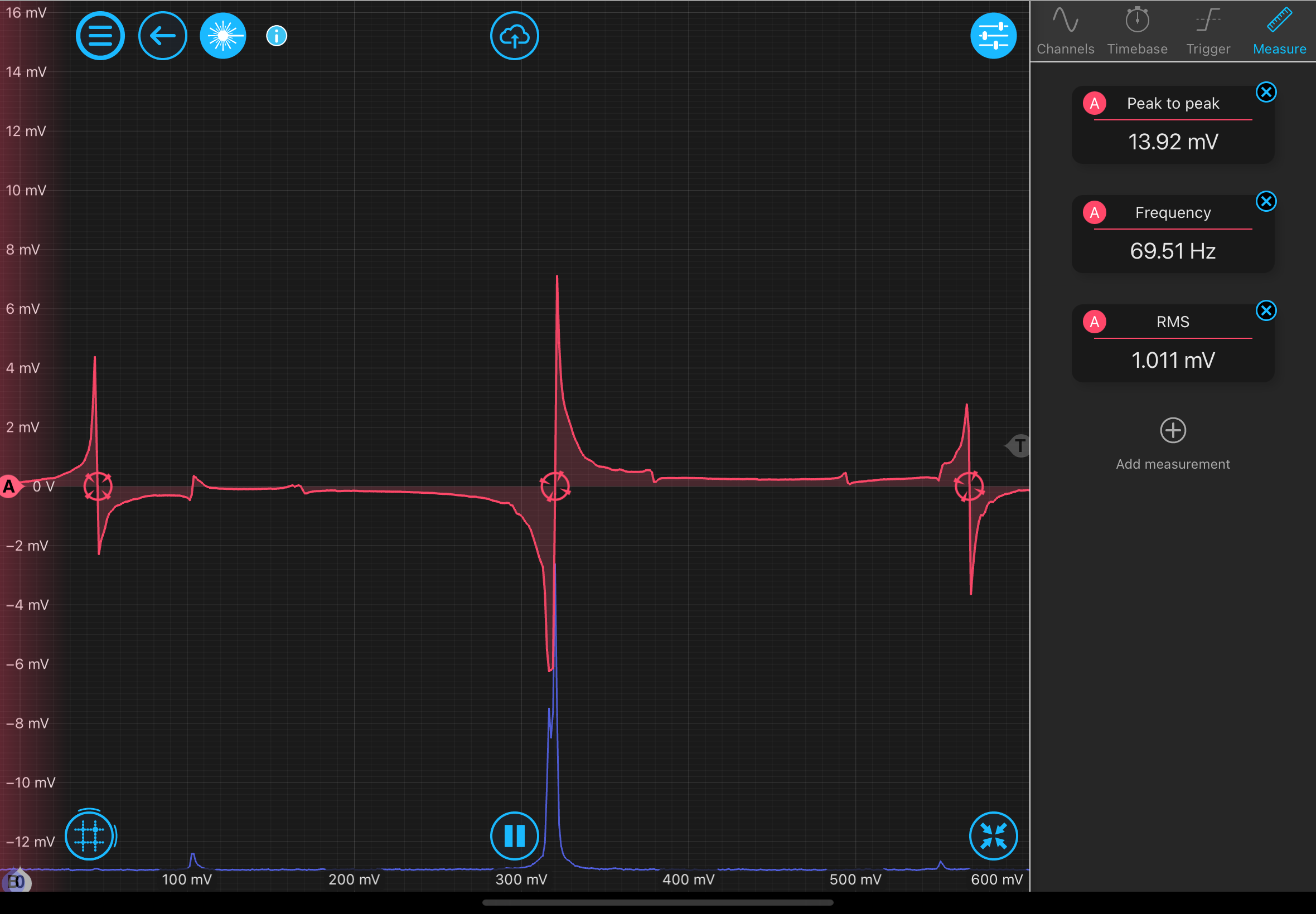
Using the PDH error point offset (~5 mV) and the output offset (100s of mV) as the kick point seems to kick the laser frequency in a way that is creating some non-linearities so that the data never matches up with the expected decay function. I've found a way that seems to get around this. Locking the cavity and shifting the output offset by 10 mV breaks the lock long enough to see a decay. I think the take away here is we need a more consistant way to fast shutter the 1550 light going to the cavity.
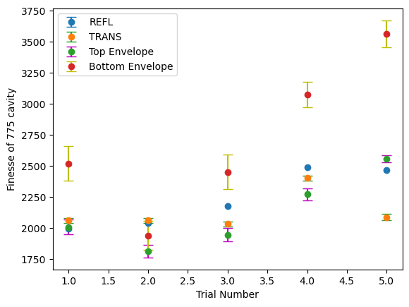
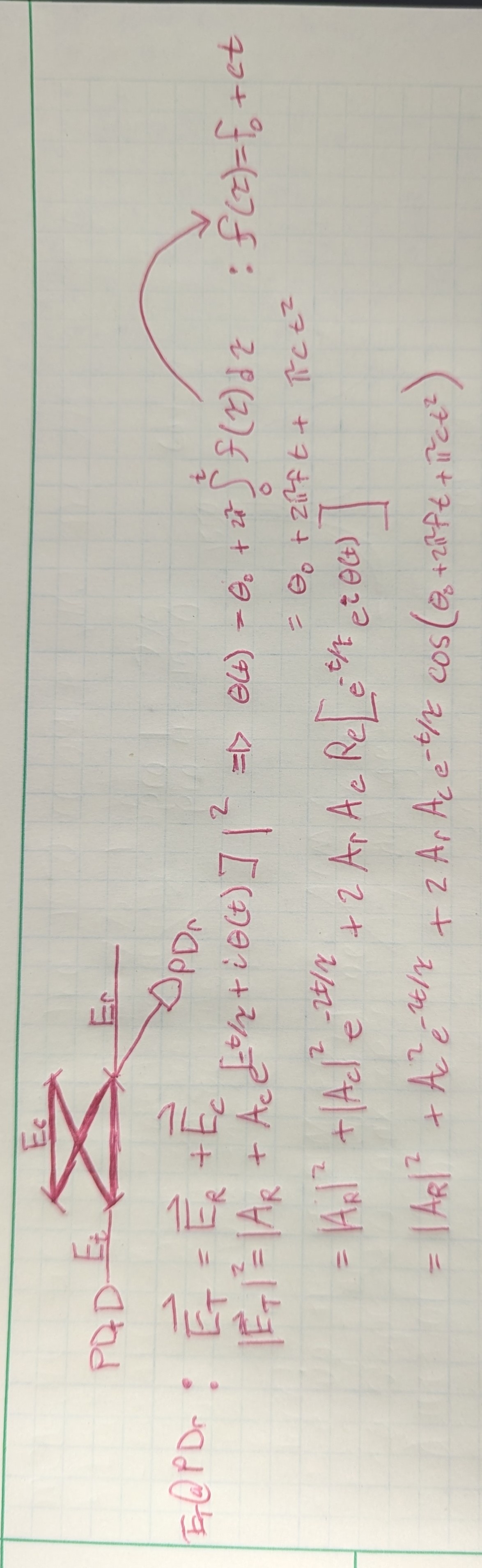
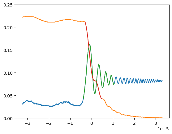
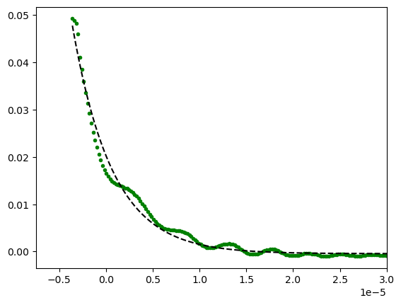
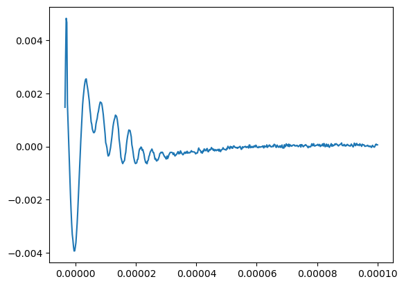
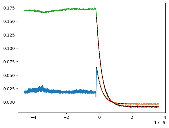
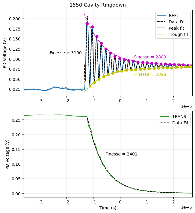
Attached is a fit a plot showing the fit to the decay envelope, the full REFL, and the full TRANS signal with the corresponding finesses from these fits. I am unsure at the moment which one should be interpreted as most accurate, although I'm leaning towards the REFL envelopes.
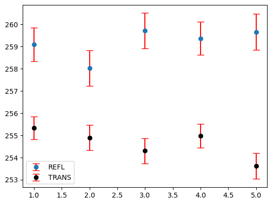
I've taken 5 more of these measurements to average over. Will process these monday morning.
Attached is all 5 trials using this method. Separated by type of fit/measurement.