The 775 nm and 1550 nm transmission peaks in the output filter cavity might fluctuate over short timescales, shorter than we'd expect from thermal fluctuations. One cause could be sound waves modulating the air, which has an index of refraction with wavelength dependence.
The optical path length (OPL) = L * n, where L is the length of the cavity ( which is 2.4 m) and n is the index of refraction.
\[ n = 1 + (n_0 - 1)\frac{\rho}{\rho_0} = 1 + (n_0 - 1)\frac{P}{P_0} \]
Where the variables with the subscript 0 are the nominal values. For 775 nm light, n_0 = 1.000275, while for 1550 nm light, n_0 = 1.000273, accoring to this website.
Thus,
\[ n_{\text{rms}} = (n_0 - 1)\frac{P_{\text{rms}}}{P_0} \]
\[ P_{\text{rms}} = P_{\text{ref}} 10^{L_p / 20} \]
P_ref = 20 uPa
\[ OPL_{\text{rms}} =L(n_0 - 1)\frac{P_{\text{ref}} 10^{L_p / 20} }{P_0} \]
This formula agrees with this post, up to a small multiplicative factor of 1/n^2.
Let's assume a moderately loud L_p = 60 dB
775 nm OPL_rms = 1.32*10^-10 m
1550 nm OPL_rms = 1.31*10^-10 m
\[ OPL_{\text{rms, diff}} =L(\Delta n)\frac{P_{\text{ref}} 10^{L_p / 20} }{P_0} \]
So the difference in OPL_rms between the wavelengths is 1*10^-12 m = 1 pm.
[Daniel, Torrey]
-We moved the AOM RF power drive to moku 4 channel 4. A 10 db attenuator is on the end of it and the amplitude coming out of M4CH4 is maxed (2 Vpp) which yields 632mVpp the previous drive amplitude was 600 mVpp. This should functionally limit the AOM being destroyed, outside of turning the channel output to +14dB mode.
-We put a large scan amplitude into the laser frequency to see multiple FSRs on the 775 path. We then measured the difference between the FSRs and they disagree by 0.4% in one measurment and 0.8% in another. The scan was ~1 Vpp.
Some future steps:
Calculate 775 nm finesse with ring down using AOM
Look at 1550 nm transmission using 775 nm lock when the 1550 nm light is resonant and half way between resonances
Calculate 1550 nm to 775 nm peak drift using PDH error signal of 1550 nm light. Likely requires better 775 nm lock
Based on yesterdays post, we can fit a lorentzian to the tranmission peaks and find the FWHM. Using parameters of the laser we can find cavity BW in frequency for each wavelength of light. We can also calculate the expected finesse based on the quoted reflectivities of the superoptics. These values are as follows.
775 BW (measured) | 102 kHz |
1550 BW (measured) | 24.4 kHz |
775 finesse (measured) | ~600 |
1550 finesse (measured) | ~5000 |
775 finesse (expected) | 313 |
1550 finesse (expected) | 3556 |
The ratio between the measured finesses, ~8.35, is very acurate as this doesn't depend on the calibration of the actual value. I think Lee previously mentioned he expected the ratio to be about 10. The accuracy of the actual value depends on the accuracy of laser parameters which we know could be like +/-20%.
[Daniel, Torrey]
-Going to move AOM frequency to calibrate offset from 1550 nm light to 775 nm light.
Frequency Generator at 80 MHz: 101 uW at fiber output to OFC
Frequency Generator at 78 MHz: 130 uW at fiber output to OFC
We remeasured the required shift at 80 MHz. Screenshot attached. Shifted to 78 MHz AOM shift. and measured the required shift.
78 MHz, fiber input power: 500 uW
Calculated that 1550 nm and 775 nm resonances through cavity would align with a phase shift of 59 MHz (modulo ~31-33 MHz); can't go to 92 MHz with the Siglent signal generator (max 80 MHz)
:After shifting AOM input frequency to 59 MHz, realigned mirror back into AOM and fiber coupler.
240 uW into fiber, 74 uW out. The AOM is less efficient at 59 MHz according to the spec sheet and in this data. Checked alignment of modes in frequency space. Seems to be an error in the calculation (about a factor of 2). Going to increase frequency past 80 MHz instead of going lower, because the efficiency drops off significantly below ~45 MHz according to the specs.
We need to use a different signal generator to go to the calculated 104 MHz signal required to make the 775 nm and 1550 nm transmission peak align. We strung up a cable to use the moku as the signal generator for the AOM. We aligned the 104 MHz beam into the fiber, optimized the frequency of the AOM to 104.37 MHz to align the peaks.
After this we have confirmed 775 and 1550 light are resonant in the cavity at the same time.
We placed the 775 nm light approximately halfway on the 1550 nm light, locked the cavity on the 775 nm light using the laser frequency, and then observed the drift of each wavelength's cavity transmission over time. This drift occurs if the 1550 nm wavelength changes over time relative to the 775 nm wavelength. Attached are two time traces of the logged data of the 1550 nm and 775 nm cavity transmission.
Separately, we also have a measure of the transmission peaks while scanning the laser frequency with a triangle wave with a 10 Hz frequency to calculate the different finesse for each wavelength, will update.
[Daniel,Torrey]
Since we have a frequency shift on the 775 light we need to experimentally determine how far apart the two 0,0 modes are in frequency space. We can do this by using a large scan amplitude (10 HZ triangle wave on laser frequency @ 2 V) to scan over a full FSR in the cavity. This scan shows the transmission peaks from the two different beams arriving at the PDs at different times. We have confirmed these peaks are at distinct voltages.The 4 labelled beams are the two FSRs for each light source. Shifting the AOM drive frequency has the effect of moving the two blue peaks (775 light) left or right, but the spacing between the two peaks remains constant (this is the FSR and is defined by the cavity length). Here, we want to determine how much we should move the frequency of the AOM drive so that one red and one blue peak match up. This can be calculated by just using the fraction of the FSR
\[ redleft = 70.68ms \]
\[ redright = 39.03ms\]
\[ blueleft = 59.90ms\]
\[ blueright = 44.39ms\]
\[ reddiff = redleft - redright\]
\[ bluediff = blueleft - blueright\]
\[ FSR = 125 MHz\]
\[(blueright-redright)/reddiff*FSR/2/1e6) = 10.58 MHz\]
\[(redleft-blueleft)/reddiff*FSR/2/1e6) = 21.28 MHz \]
The 10.58 MHz number is closer, and is to match up the two right peaks, however this means increasing the drive frequency. The current RF source is already at a max in frequency. We could use an alternate RF source like the moku or shift back to 80 - 21.28 = 59.72 MHz. Additionally, naivly one would expect that in one direction the required frequency change would be (80 Mhz *2 - 125 MHz) /2 = 17.5 MHz or . This discrepency comes from additional phase pick up from the coatings on the super optics (the coating depth is many wavelengths deep, so the shift is actually something like in the GHz but you this number would be the remainder after dividing by the FSR).
In JamMt, I took the current AOM solution and added a thick lens (index of refraction = 2) to act like a concave mirror to redirect the beam into the same spot in the AOM. Because the beam is so small at the mirror, the curved mirror does not change the wavefront much at all. A 1 m focal length lens could be added to help the mode matching into the fiber. See attached photos.
Hi, nice to meet everybody! I'm Javier Contreras, the new FPGA developer at Fermilab.
Just sharing what I wrote down during our June 4th meeting. Sorry it's a bit verbose as I'm still new to the project and trying to figure everything out. Please add your comments!
Summary: Need to consider higher bit depth than 16 to ensure control loop stability. Biquads are important to compensate piezos' response. I'll continue work on setting up hardware simulations that'll help us figure out the optimal implementation of the filters.
--------------------------------
FOM for implementation must consider not just noise but also coefficient resolution => 16 bits is not enough!
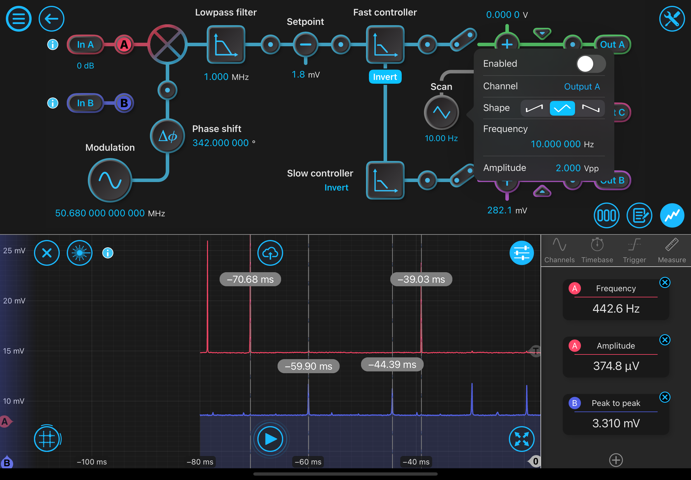
10 MHz for a sample rate is a good "middle value". Want the low pass at 10Hz. Similar to a SR560 control loop, with high-gain at low freqs with 1/f behavior.
10Hz is at a millionth of the bandwidth! When sampling and wrapping s into the z domain, the pole ends up dangerously close to |z|=1 so we need good precision.
Having an input signal with around 16 or 24 bits might help us save internal bits as the LSBs of high-precision multiplications are eventually truncated anyways.
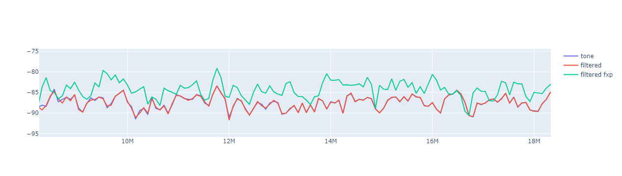
Must produce a test suite of filters for the Moku with different bit depths to compare noise. Caltech team will provide Ai and Bi coefficients. FNAL has been using scipy.butter.
DF1 vs DF2 is a matter of fixed-point vs floating point and dynamic range vs. noise. Each one has benefits and drawbacks but it seems DF2 is generally prefered.
Once I get the Vivado simulations running I'll seek to test all the bit possibilities and compare latency vs noise vs area.
Interlacing DSPs will likely be necessary. Can also take advantage of the FPGA clock being sufficiently higher than the sampling rate.
Moku provides lots of options but many of them aren't performing the best they could. We want to beat the Moku at the things we want to do.
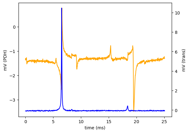
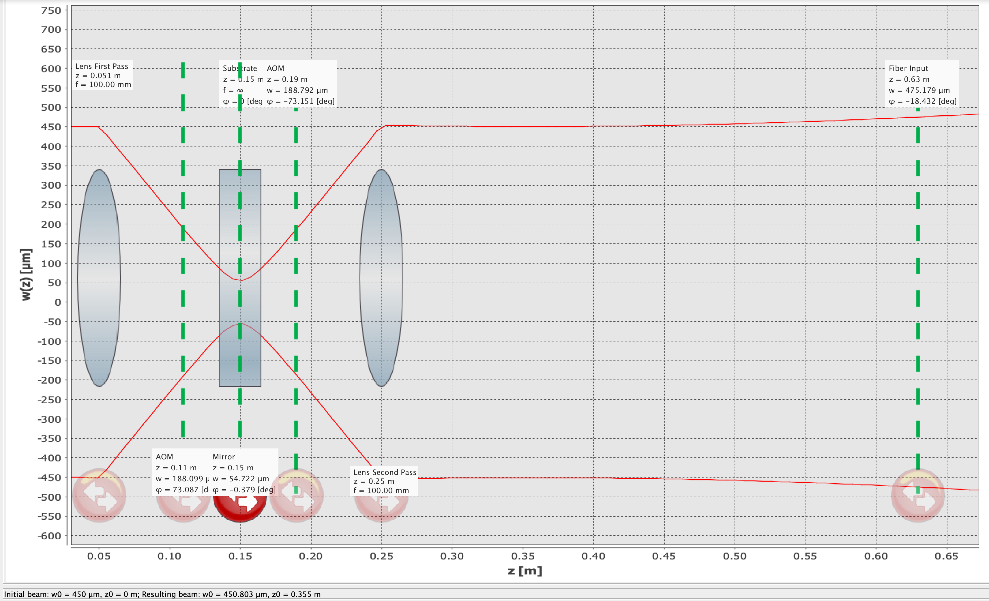
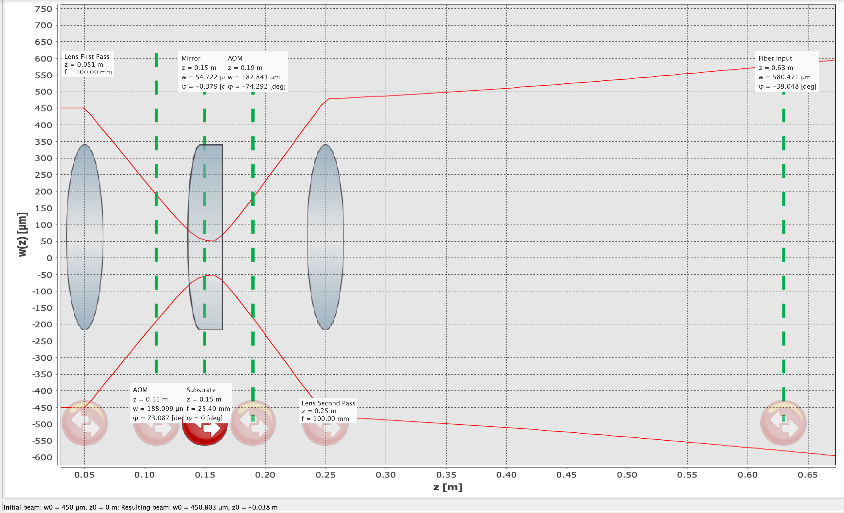
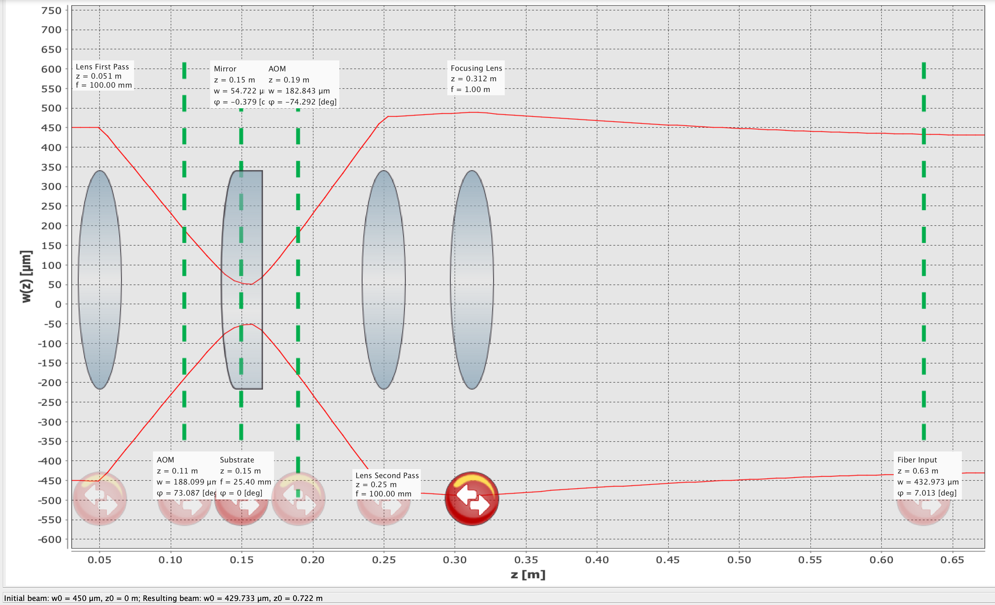
Lock cavity to 1550 & 775nm via an AOM that's traversed twice and lambda/4 shifted. 40% efficiency on each pass, also diffraction losses, but still able to lock the cavities.
Main cavity needs to be stable down to the pm regime. Feedback ctrl must stabilize the cavity against effects of air and sound.
1-2 kHz not enough for ctrl loop. Best efforts w/Moku reach ~8kHz. Piezos have annoying resonances.
Donut-shaped 01 Gauss-Laguerre mode looks nice!
3-4 biquads will be necessary to compensate the response of the piezos. Some to remove notches, some for resonance. Improve problematic 1-2kHz region.
Goal with FW is to have 2-3 channels with as many as 10 biquads. Not necessarily all channels with 10. Consider switching, multiplexing & swapping. Could have 3 sets of filters multiplexed 30x contingent on FPGA Clock vs Sample Rate.
If we use 10 filters, we introduce more pipelining latency. Better to move data to memory ASAP and do the routing logic from that instead of buffering and introducing more latency.
LIGO uses EPICS as a DAQ solution; worthwhile to use it as middleware. ACORN is "EPICS on steroids". MEDM is deprecated.
Caltech will be working on this middleware based on LIGO, also the "Guardian" framework which manages such EPICS middleware and sequencing.
Ryan has a similar solution and integrating it would only need registering to the proper EPICS variables.
Chiller arrived at FNAL, and Chris sent "the machine". There's a lab warm-in coming at Caltech! In around 1-2 weeks. Work is pending on a water exchanger. Matt Hollister is moving on to industry work :'(.
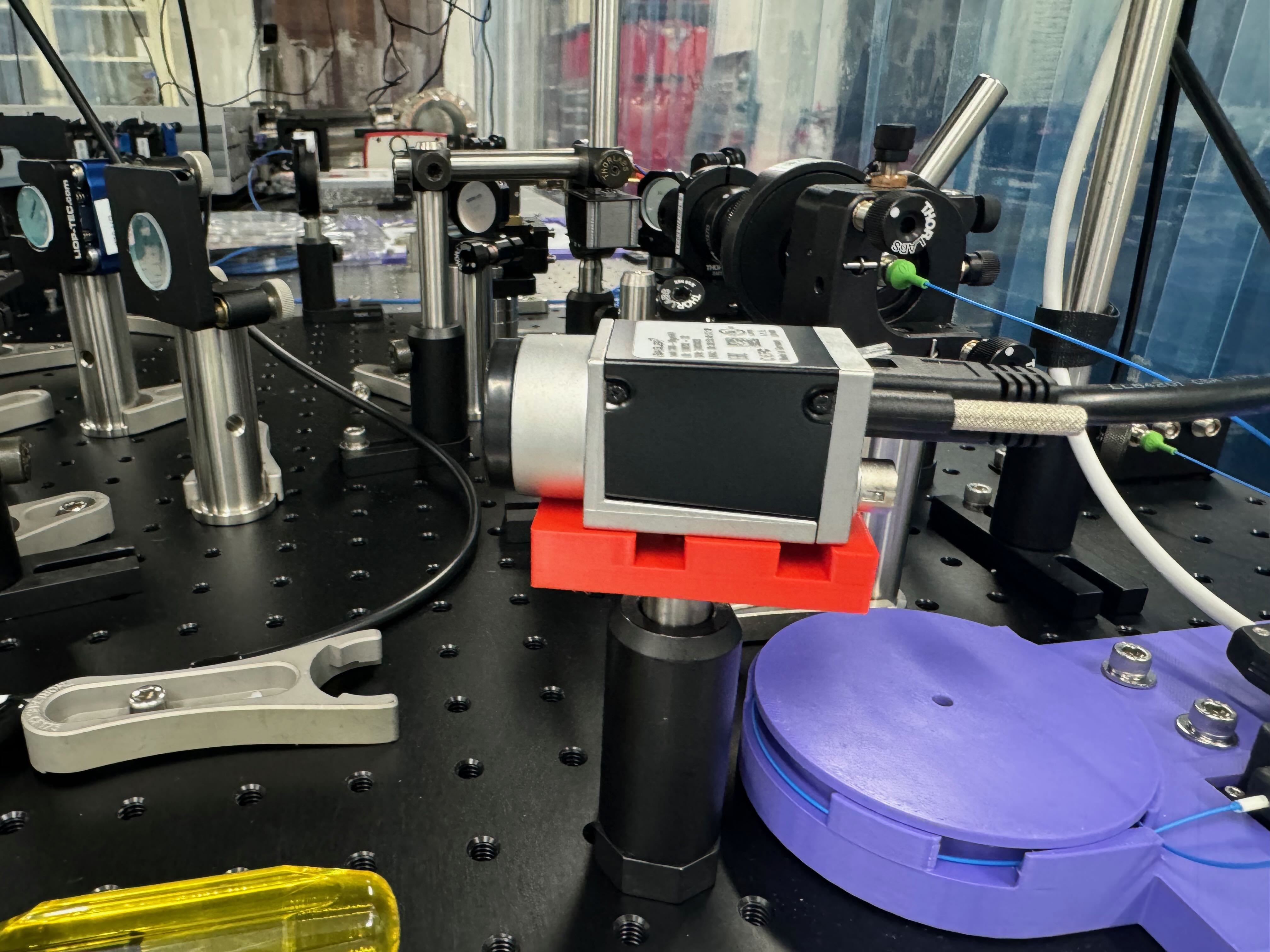
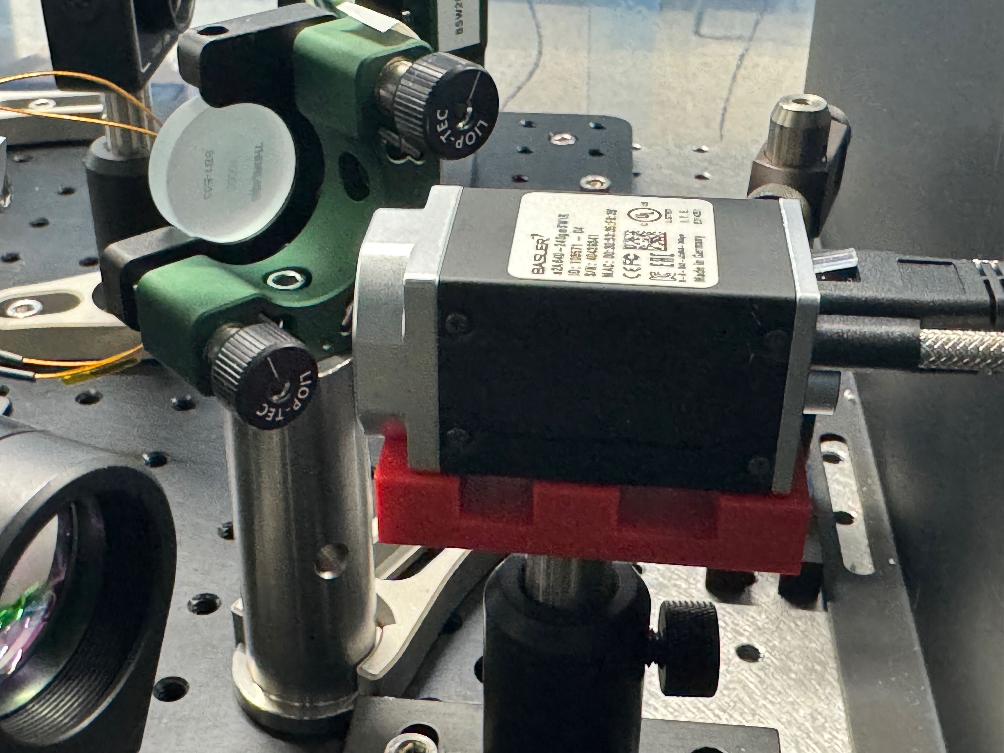
10 more IR cameras & pico controllers to be sent.
-Achieve good laser lock with 775 light. Noticeable second beam on camera when locked. Not sure where its coming from but it should be diagnosed.
-Used plastic tool that comes in the tunable inductor kit to maximize the error signal amplitude by tuning the inductance. Error amp increased from 3mV pp to just over 5 mV pp. Note this still needs to be done on the 1550 path. Need alignement first though.
-Reprofiled the 775 light going to the caavity. MM is worse. May need to move some lenses.Note though that the power is very low going into the cavity which reduces the acuracy of using the beam profiler.
-Dramatically improved alignment for 775 using cavity mirrors. 0,0 is dominant enough to justify not moving lenses for now. Error amplitude in reased to ~9.5 mV. TRANS PD was misaligned as well.
-The 775 light can be seen on the SWIR camera. I used this for initial alignment by walking the 1550 beam to get close to the 775 beam that is on resonance. This was successful and we now have 1550 flashes in the cavity! The orientation to achieve this however is having the reflected beam go very high such that it is missing the mirrors that steer it to the REFL pd. This needs to be solved.
The twice shifted light via the AOM has been aligned into the fiber that brings the light to the filter cavity. It looks like alignment is slightly worse after messing with the fiber, alignment touch up is needed. There is also a ghost beam from somewhere now that should be diagnosed. 775 light is now ready though.
Just so people know, there is a constant in frequency sine wave on the error signal of the 775 reflected light. After talking with Lee, he suggested it being a beat note of the EOMs. I turned off the 1550 EOM and the beatnote in the error signal disappears. Something to keep in mind going forward.
The notebook DirectFrom2FxpDemo.ipynb simulates a digital biquad filter with fixed point math. For 16-bit inputs and outputs, 16-bit coefficients, and 32 bit accumalation terms, there is a 4 dB additional noise added.
4 dB seems like a lot for this kind of thing. Do you have a copy of the notebook?
I have one sd card where pynq runs the demonstration program analog_echo correctly. I sent another one to CIT and Jeff reports that it does not work. I made a seoncd SD card using the pynq image from here: https://github.com/dspsandbox/Pynq-Redpitaya-125 and it does NOT work.
I checked the checksums of the files on the two pynq distributions and found no difference.
I then made an image of the working sd card. It fails in the same way. This call in analog_echo.ipys
ol.axi_gpio_0.channel1.write(val=offset_1, mask=0xffff)
crashes the os
Now swap the SD cards between the two RedPitayas. The "good" card boots as ip address 192.168.68.113 but fails.
The "cloned" card boots as ip address 192.168.68.111 and it works.
Therefore, I conclude that RedPitaya 00:26:F0:B9:F8 is a good board and 00:26:32:F0:AC:E6 is broken.
Swapping the cards back confirms this. So, I have two good sd cards but only one good RedPitaya board. I suspect that the RedPitaya I sent to CIT is also a bad board.
If we add a mirror such that the frequency shifted beam is reflected directly back irrespective of the drive frequency, then the twice shifted beam will go exactly back to the origional incident beam on the AOM. See the attached sketch. A spherical mirror with radius of curvature equal to the distance to the end of the AOM should do this.
For our setup, the mirror is about 4 inches (100 mm) away from the AOM. Therefore, we should use a dialetric coated or silver coated (cheaper) mirror. Newport has worse options.
The addition of this mirror would change the mode matching solution. I think this change is worth it.
I have calculated the predicted angular and linear deflection from changing the AOM drive frequency.
The setup:
Assume the beam is aligned for some nominal offset frequency such that the angle of incidence on the (thin) crystal is equal to \theta_{B, i} (B for Bragg, i for initial setup). This angle. is linear with frequency. Assume the unshifted beam goes through and is blocked and the frequency shifted beam, which has an angle of 2*\theta_{B, i} with the unshifted beam, is reflected back to the same spot on the crystal. Then assume this beam is either unshifted again, or shifted again (so twice the frequency shift). See the images from Steck's Optics Notes section 13.2.
Now assume the rf frequency is changed. Now the shifted beam makes an angle of 2*\theta_{B, f} with the unshifted beam in both directions. Assume nothing else, such as the alignment of the beam incident on the crystal or the alignment of the mirror, has changed. I have calculated the angle of transmission of the once and twice shifted beams. See my sketch attached.
Twice shifted:
\[\theta_2 = 4\theta_{B, f} - 3\theta_{B, i}\]
Once shifted:
\[\theta_{1, \text{out}} = 3\theta_{B, i} - 2\theta_{B, f}\].
So the twice shifted beam is twice as sensitive to the frequency shift. However, the frequency shift required is half, so it does not matter which beam is used.
The linear deflection, for a AOM to mirror distance l = 5 in, a wavelength \lambda = 775 nm, a crystal speed of sound v_{rf} = 4200 m/s, and a frequency shift of 40 MHz.
\[\Delta h = \frac{l \lambda}{v_{rf}}\Delta f_{rf} \approx 1.4 mm\].
There are lots of triangles and some AOM physics that is new to me, so there is a decent change I have messed up somewhere.
We are imaging the beams after they go through a lens, so this might distort the picture presented.
-Total power input on AOM - 1.3mW
-Use iris to block unshifted light - 250 uW
-Current AOM settings: 2W amplifier, 350 mVpp, 80 MHz - 20% efficient on first pass.
-74uW total power after PBS
-17uW blocking main beam with iris - ~23% efficient on second pass.
-optimized the quarter wave plate to maximize reflection back through the PBS. total power after PBS is 190 uW
-39uW blocking main beam with iris.
-Attempted to improve efficiency by increasing RF drive power. 600 mVpp RF drive now. This should be providing approximately a watt to the AOM now.
-1.5 mW total light
-600 uW blocking with iris to give 40% efficient first pass.
-585uW total on PBS reflection, 260 uW blocking with iris to get ~44% efficient with second pass.
-A tube based BS holder is probably the best bet to see the shape of the first pass and second pass beam simultaneously.
[Lee, Torrey]
-Low voltage high amp draw from RF power source
-Checking the power of the RF drive on the aom. Within limits with some loss through BNC and factor of two from termination.
-Tested everything. The homeade power source was shorted.
-Re-soldered power source, plugged everything in, and we have frequency shifted light. More to follow after lunch.
-Installed 1/4 waveplate and mirror to reflect back through AOM.
-Align to see the twice shifted beam. Can confirm this beam is from the difracted beam as both dissapear if you turn off the AOM RF drive. Also can use iris to block the normal beam and pass the first order diffracted beam.
-There is VERY little clearance for the beam due to the AOM RF drive cable. The cable is almost exactly at 4 inches from the breadboard. Thinking about using an AOI greater than 45 degrees to align into fiber. The thorlabs BB1-EO3 shows good reflectance at low AOIs but not at large ones.
-The current configuration on the table can be seen here. The twice shifted beam is fairly astigmatic so alignment can most likely be improved.
First, I downloaded the image found here (DSP sandbox PYNQ-Red Pitaya) and wrote it to a micro SD card. After that I connected the Red Pitaya to:
1. Power (micro USB)
2. Serial connection to computer (micro USB)
3. Ethernet connection to router
Then, I went to "http://pynq:9090" I was met with a jupyter notebook password screen. The password is "xilinx".
In the jupyter menu you can open a terminal to access the red pitayas Linux system. I followed the instructions here (PYNQ getting started) to change the host name to "pynqpitaya"
I ran the command "ifconfig". There are multiple IP addresses. Why?
The address that allows one to ssh or scp onto this red pitaya is 192.168.50.14, which corresponds to "eth0" rather than "eth0:1"
After using scp to get the analog echo bitfile and notebook from Chris' logpost onto the board, I ran the notebook. The first cell runs successfully, and a blue light comes on the red pitaya. However the cell with the write statement never executes. When I measure the DAC outputs on an oscilloscope, they measure about +1V and -1V. No response is seen to an input pulse on ADC 1.
Today I tried this procedure again with a new SD card, and the result was the same. There is still no echo from the Red Pitaya. Here are three possible explanations:
1) The Red Pitaya I have is broken. I don't like this explaination because I am able to log into the Jupyter notebook and run the first cell without any issue.
2) There is something wrong with my procedure for writing the PYNQ image to an SD card which I have repeated each time. Like the last idea, this seems implausible due to the fact that the booting the system and accessing the jupyter notebooks works fine.
3) there is some difference, either between the bit file and the board, or between the bit file and the PYNQ image, which is causing things to work differently than on Chris' system. My board is a Red Pitaya STEMlab 125-14 LN. The PYNQ image is Pynq-Redpitaya-125-14-3.0.1.img
I 3D printed a Holder for the Basler ace GigE C camera, which we are using to image the 775 nm light. The holder interfaces with 3 M3 screws on the bottom of the camera and allows for a #8 socket head cap head screw to be added. The bottom of the holder is 1 inch from the center of the camera. The holder has some slots to allow for air to flow below the camera for ventilation and hopefully keep it cooler. I'm not sure of the efficacy of this since the other 5 faces were open on the other camera and it still got quite hot (although still within spec).
Attached are SolidWorks and STL files for the part I made and the camera, plus a PDF design of the camera.
I printed another mount with wider M3 holes for easier insertion. See attached files.
For a future version, perhaps the M3 holes shouldn't be counterbored so there is less filament to clean up. This would require the correct M3 screw length, which might be harder to find for a longer screw.
I redesigned and made a mount that allows for a C mount to be attached to the front so that ND filters and lenses can be easily added.
See attached files.
I 3D Printed a Basler ace 3 GigE Camera Mount. It sets the center of the camera 1 inch above the bottom of the mount.
Attached are the 3D printed part and a recreation of the Basler ace 3 GigE Camera as SolidWorks and STL files.
I redesigned and made a mount that has grooves for ventilation since the camera gets quite warm and that allows for a C mount to be attached to the front so that ND filters and lenses can be easily added.
[Daniel, Torrey]
We can calculate this in an alternate way avoiding using any kind of calibration on the laser. The FSR, measured in time on a cavity scan, is 31 ms and 15.5 ms for the 1550 and 775 light, respectively. The FWHM or bandwidth in time is 1.86e-5 s and 7.8 e-05 s for 1550 and 775 respectively. This means we have a measured Finesse of 1660 and 221 for 1550 and 775 light, respectively. These agreed much closer with the expected values above.