[Ian, Torrey]
We have aligned the 775nm light path and cavity mirrors to the point that we have a large a mount of 0,0 mode flashing! We did this by first removing the input coupler (OFCM3 see labeled photo in post 11575) from the cavity so we could see the beam inside the cavity without strong reflections. The using the 3D printed jigs to get the beam close to the proper alignment for the other three mirrors. After we had the alignment correct on those we installed the input coupler (OFCM3). Then we walked the beam around by moving the 775 nm input coupling mirror (OFCM3) and the one diagonal from that (OFCM2) until we saw two beams on the transmitted photodiode. Then we continued to walk it until we saw three. making these overlap on the photodiode made use see HOMs. We played with the alignment walking the beam until we saw the lowest order 0,0 mode flashing with the others.
After we saw the first mode flashing we installed a 50/50 beamsplitter on the transmitted path allowing us to use the Bassler camera that we had been using for alignment and installed a transmission photodiode (Thorlabs PDA50B2). This photodiode is only rated to go down to 800 nm but it has enough sensitivity for the basic lock. We will need to replace it when we get new PDs. We also realigned the reflected beam path because that was now off from our alignment.
With all of those fixes and installations of new BNC cables (which we had to make out of a number of shorter ones. we should buy more) we were able to get a rough lock on the 0,0 mode shown in first attached image. We think that there needs to be adjustments to the mode matching to make the lock robust.
Post updated from earlier by Ian
This is a list, mostly for my self, of components used in the first filter cavity that are suboptimal, and should be replaced when the new components arive.
-1811 PD for REFL/PDH locking.
-PBS for power attenuation on 1811 PD (stolen from SHG sled). Causing power modulations when the fans are on.
-lots of BNC cables strung 2 or 3 together instead of a single long cable
Alignment is poor. I am still searching for flashes with the 775 light. The first pass beam can be seen with the NIR camera but nothing else.
The attached zip file has the three files required to run the demo on a RedPItaya running pynq.
It wors like this: Read from ADC1. Send bits to two paths. Add offset_1 and send to DAC1 and add offset_2 and send to DAC2
The notebook demonstrates how to run it, and how to set the offset values.
I tested it by inputting a square pulse and measure a latency of 10 uSec.
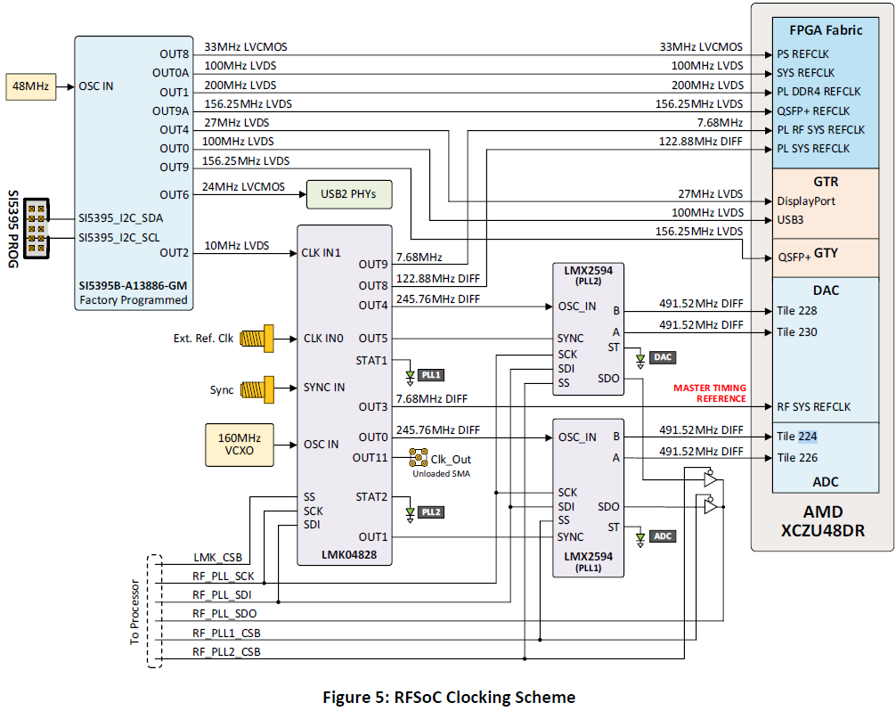
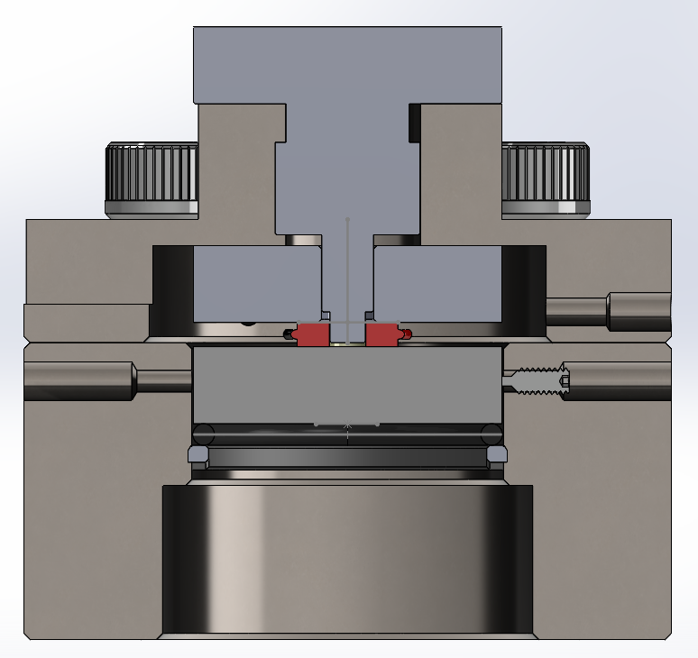
Attached is a block diagram describing the behavior of a DSP system permforming feedback control for the Pound-Drever-Hall (PDH) frequency stabilization technique. This block diagram is based on Liquid Instrument's laser lock box, which we have been using to lock our current cavity.
There are two modes of operation: 'scanning mode' and 'locking mode.' When the toggle (on the right side of the diagram) is down, we are in 'locking mode' and the control loop is closed.
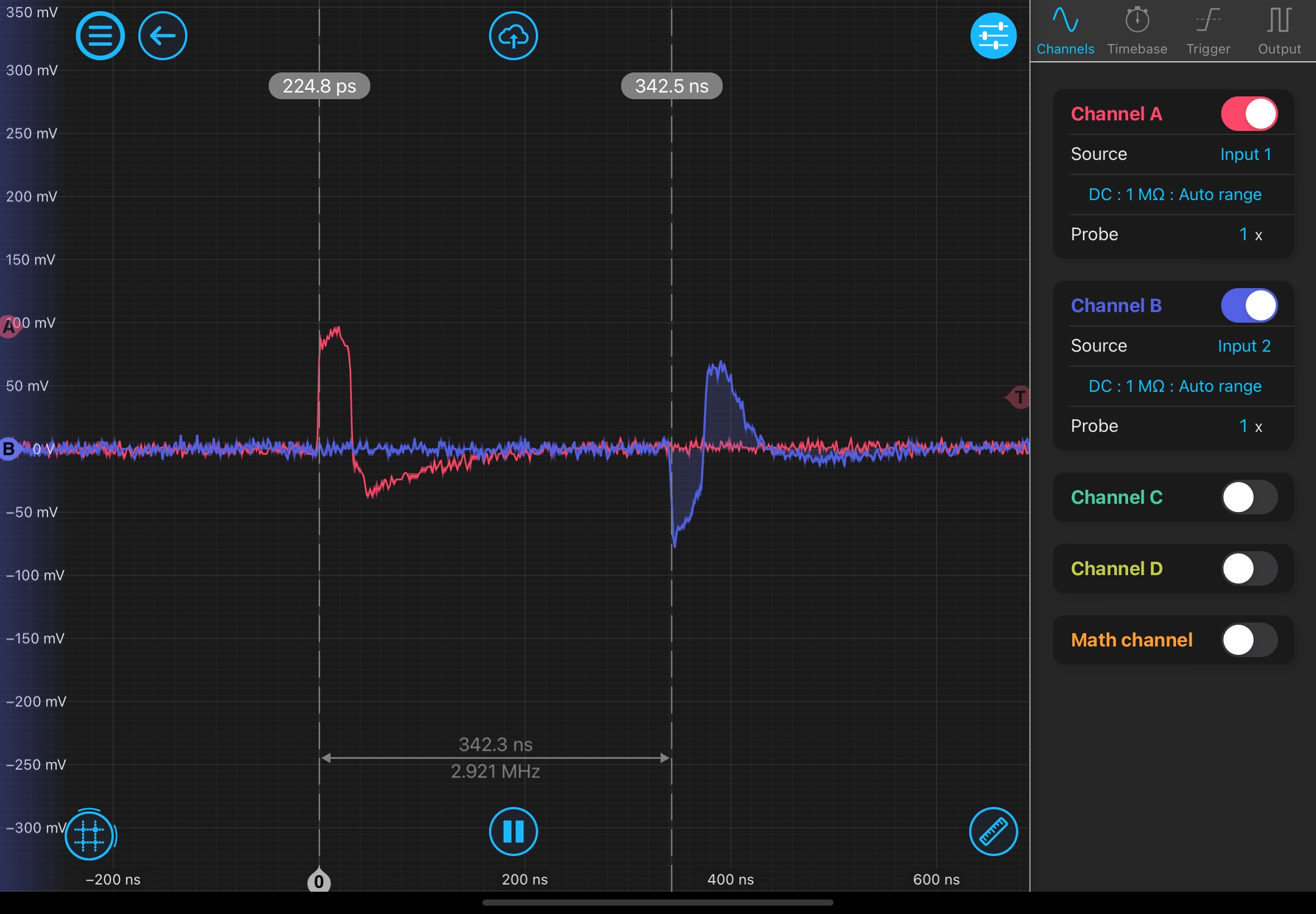
In locking mode there are two main tasks. First, we must obtain the error signal from the incoming photodiode signal by demodulation. We mix the incoming signal with the modulation tone, (with an adjustable phase offset) then we low-pass filter to remove unwanted high-frequency signal coming from the mixing. Then we subtract the desired setpoint from this signal to obtain the error signal. At this location, the error point, we want to be able to take time series of the values. These timeseries will be used to evaluate the characteristics of the loop and to make the transition from scanning mode to locking mode. Next, the error signal is passed through a series of biquad filters (the controller) to create the signal to be sent to the actuators. A constant offset is added to this signal and it is sent out to the actuator.
In scanning mode there is no feedback. Instead, the actuator voltage is swept by the sawtooth generator, and the error signal is monitored at the error point. Using the timeseries of the error signal during this sweep we can adjust the value of the constant offset and toggle the switch, exiting sweep mode and closing the loop.
To meet the requirements of the GQuEST experiement, we want to lock the cavities with a 10kHz unity gain frequency, and a 'low enough' root-mean-squared displacement. We will continue to work to understand what is 'low enough' and how this translates to FPGA specs, but until then here is a list of our best guesses at the approximate desired stats. These are based on the stats of the Moku and a few calculations, some of which are found in this log post and its comments. In particular, as the filter sample rate is increased, the number of bits required for the filter coefficients will increase as well.
Filter sample rate - 25MHz (Moku IIR filters use 40MHz)
ADC/DAC bit count - 16bits (Moku combines a 10 MSa/s, 18-bit ADC and a 5 GSa/s, 10-bit ADC)
Biquad internal bit count - 32bits (Moku uses 48bit filter coefficients)
Total input-output latency - 1us (Moku has around 1us)
Can you add a sampling point before and after the SOS so that I can analize how well they are preforming?
Jeff, this looks good. What about timing stability? How stable do frequencies need to be? For more than one PDH control loop, are the feedback loops independent or do we need them to be synchronized?
Attatched is a good reference on Pound-Drever-Hall stabilization
Attached is a powerpoint by Matt Evans on digital filter implementations, including a low noise second order section.
I 3D printed a Holder for the Basler ace GigE C camera, which we are using to image the 775 nm light. The holder interfaces with 3 M3 screws on the bottom of the camera and allows for a #8 socket head cap head screw to be added. The bottom of the holder is 1 inch from the center of the camera. The holder has some slots to allow for air to flow below the camera for ventilation and hopefully keep it cooler. I'm not sure of the efficacy of this since the other 5 faces were open on the other camera and it still got quite hot (although still within spec).
Attached are SolidWorks and STL files for the part I made and the camera, plus a PDF design of the camera.
I printed another mount with wider M3 holes for easier insertion. See attached files.
For a future version, perhaps the M3 holes shouldn't be counterbored so there is less filament to clean up. This would require the correct M3 screw length, which might be harder to find for a longer screw.
I redesigned and made a mount that allows for a C mount to be attached to the front so that ND filters and lenses can be easily added.
See attached files.
[Torrey, Ian, Alex, Daniel]
We turned off and unplugged many expensive/critical electronics systems in B102 in anticipation of the Power Cycle of the entirety of Bridge early next morning. This includes the SHG, amplifier, seeder, mokus, and piezo driver.
Things are back on.
[Torrey, Ian]
Afternoon work:
- M3:SN17 super optic is install in a flexture mount for position FCM3 in the filter cavity. https://wiki.mccullerlab.com/DCC/S2400001#chapter_dcc_s2400001_45 is updated accordingly. Both the case and flexture mount are labeled.
-I am going to keep moku 4 as the 1550 nm wavelength controller for now. Moku 1 will be 775 nm, i.e. PM driver, TRANS/REFL for 775 filter cavity
-1811 is aligned for the 775 REFL path. We dont have 775 ND filters atm. Cant do a make shift one out of a 775 PBS as we dont have any of those either. Or 775 HR with no frosted back. May need a 775 general use order to be placed.
-We are going to use a random optic we found from the previous groups leftovers to attenuate power in the mean time. It is 852 HR with no frosted back. Tested, provide sufficient power supression.
-SHG temperature controller, laser amplifier, and seeder have been shut off and unplugged in preparation of the power loss tomorrow from 4am to 8am.
Bullet point notes on the filter cavity sled as things are moving around as we prepare for 775 nm.
-Particle count since super optics in use: 0/0/0
-To allow for 775 light transmission I have moved the 1550 TRANS PD to be on the opposite side it was previously. See attached photo.
-780 HR steering mirror and 50:50 BS set up, as well as the NIR basler camera to see 780 transmission. Location set up for 780 TRANS PD when they arrive.
-NIR basler camera confirmed working on pylon viewer. Had not been previously tested. Waiting on a 3D printed mount from Daniel to put it on the table. Daniel updated the print to include slots for ventilation.
-1811 PD installed for 775 REFL. Note that this PD is not made for 775 and will be inefficient. Hopefully it will suffice. Additionally, we will need an ND filter in this path depending on how much 775 power we put into the filter cavity. In its current configuration there is <1 mW. 1550 saturation power is 55 uW though. Will likely need at least an OD1 ND.
-Particle count at end of morning work: 0/0/0
The attached zip file was prepared for me by Martin di Federico. It exercises the DAC and ADC channel by copying the bits read from an ADC to the DAC. After following his instruction, I input square wave pulses to ADC_D and read from DAC_A. I see about 340 nSec latency.
You do NOT neet to comile the project, but just copy these files to your 4x2 board and run the notebook:
4x2_echo.bit 4x2_echo.hwh echo_test.ipynb
We'll continue working from this design to see how the latency could be reduced. The RFSoC data converter has many options to explore. In an online forum this is expected:
ADC maximum configuration i.e 8x decimation , NCO enabled and QMC enabled = 103ns (412 sample clocks)
DAC maximum configuraion i.e 8xinterpolation , inverse sync . NCO, QMC enabled = 119ns (760 sample clocks)
That looks like a total of 103+119=222 nSec but I measure 340 nSec.
Here is Martin's description of the design, reference 4x2-timing.png also attached.
Hi Chris.
I have create a project and change some stuff..
I create a project and an automated script to create it.
I will summarize
I've repeated this measurement with our SoC and get the same value of 340 ns for the delay. Attached is an oscilloscope trace of the pulse in red and the echo in blue.
I also performed a swept sin measurement of this same bit file, from 15MHz to 20MHz. The phase info is consistent with a 350 ns delay. Notably the magnitude of the returning sin wave is about half of the one sent in.
[Lee, Daniel]
We are designing a custom ring to fit around the 1.0005" diameter, 2 mm thick cylindrical mirror for the GQuEST End Mirror Correction Mount. We ideally have an end mirror that clamps the entire ring of the end mirror. The current design has the ring ID of 0.998", 0.0025" smaller than the mirror it's clamping.
I think the current design clamps the mirror too tightly where the clamps meet and too loosly away from the joint. In SolidWorks, I moved the half rings 0.010" apart, the thickness of some indium foil from McMaster. I then checked where the ring and half rings overlap. See attached photo; overlap in red. Ideally, the rings have no overlap with the mirror when seperated by 0.010" and instead overlap everywhere by a few thou when the seperation is reduced.
I propose that instead of having a smaller ID, we shift the center of the ID out by (roughly?) half the indium foil size. This way, the mirror is not compressed when the indium foil is not compressed and the mirror is compressed everywhere when the screws are tightened. As the rings move in, the mirror edge furthest from the screws experiences the full change in distance while the edge of the mirror closest to the screws only has a fraction of the ring move into it. In some ways, I think this is good because the ring will bend in around the mirror by the screws, albeit not by much.
Cavity super optics installation went smoothly.
The input and output 1550 couplers have been installed in the filter cavity (T2300191-M1-SN01 and T2300191-M1-SN02). https://wiki.mccullerlab.com/DCC/S2400001 has been updated accordingly. Note that the super optic mirrors of type "M1" do not have serial numbers printed on the cases like the rest of the types (M2, M3, and M4 do). The M1 mirrors have labels on the cases they were pulled from and on the 1'' inch spacer attached to the flexture mount on the cavity. Rough alignment of the beam is done. Tomorrow we should be able to install the final optic to complete the cavity and search for a beam in transmission.
[Torrey]
Here is a photo of the output filter cavity mirror which was in contact with the piezo.
[Torrey, Daniel]
Are we going to be limited by laser noise?
Gabrielle suggests we do this in our lab with their vacuum chamber
Initial Pressure Target: 10^-1 Torr, so no turbo
The chamber fits our cavity, but is somewhat dirty so we should clean it
LIGO has pumps, gauges
We might need to supply some flanges
We should use QPDs to measure beam location before and after
These could be in vacuum, but not necessary
To minimize vibrations, we should support the chamber with viton and turn the scroll off while taking data
There has been some confusion on the super optics part labels and their placement position in the filter cavities. This post should clarify that for my own benefit and others. Below is a list of mirrors, their printed labels, reflectivity, and curvatures, according to https://wiki.mccullerlab.com/DCC/S2400001.
Part Label | Curvature | 1550 | 775 | Quantity |
---|---|---|---|---|
M1 | Flat | 883ppm | HR | 24 |
M2 | Flat | HR | 1% | 16 |
M3 | 1.6m | HR | 1% | 8 |
M4 | 3m | HR | 1% | 8 |
Note that the part label M1, M2, etc, does not correspond to its position in a filter cavity. The proposed configuration for the first filter cavity should be (according to labpic_w_labels_updated.png):
[Torrey, Daniel]
Torrey thinks that the central axes of the piezo and the mirror are misaligned. I designed a part that aligns the small piezo and a 1/4 in thick spacer with a #8 through hole with the "piezo top". This piezo top should be well aligned with the piezo bottom that holds the mirror. I believe this should give alignment of the axes to within ~5 thou rms (3 thou from the piezo top to the base, 4 thou from the mirror in the SM1 threads, and ~1 thou from this tool).
Attached is the part file with CAM as well. I decided to make this part in a CNC Lathe for its precision compared to a 3D print. An important consideration is the radius of curvature of the cutting tool. This is why there is a notch toward the thickest part of the tool and why the levels of the tool don't match the levels of each part. If one were to 3D print this part, they should remove the notch so that there are no overhung sections.
The blue colored photo is the CAM simulation.
I also made an alignment tool for a larger Thorlabs ring piezo. This requires a larger spacer, so I made a 1/4 thick (actually ~0.24 in) ring with a 1 in OD and ~0.358 in ID, slightly larger than the 9 mm ID of the ring piezo. This ring is aluminum because I didn't want to machine steel because it's tougher.
Attached is this file (medium) and STL files for this part and the other part.
I made this part on the CNC lathe and it fits well.
I also manually made a part to align the noliac piezo. This is essentially a 0.7" long rod with a 0.47" diameter and a 0.25" thick, 0.5" diameter cap so the rod doesn't go all the way into the piezo assembly. There isn't a part file for this.
This Noliac part was too large. The noliac ID appears to be closer to 0.463"
I made a piezo alignment tool for the Noliac NAC2125-H08. The diameter of this tool is 0.460" and it fits pretty smoothly around the piezo. Attached is the SolidWorks File (with CAM as well) and the file as an STL.
The Noliac piezo is a bit loose around the 0.46" diameter part, so I printed a conical version. I would have printed a version with a smaller conical angle, but I was worried about getting the part stuck because a 1-3 degree taper is prone to getting stuck.