[Jeff, Daniel]
We cleaned the 1.33" CF to 2.75" CF adaptor plate for the PICAS 2D Rb MOT and attached the Rb Vapor Cell by hand and lightly with a ball-end 9/64" screw driver. We don't have a stubby (low profile) 9/64" allen key which we need to finish tightening, so I bought some.
We also installed and tightened the screws on a 2.75" CF tee above the vacuum chamber. I haven't figured out what I want to put on it because we don't have a layout.
Since the pressure was 5E-7 Torr, I took some data with the RGA with the ion pump and turbo still on. See the attached graphs. Some takeaways: H2, H2O, and CO2 are about 2-3x the LIGO beam tube requirement (note the old date; maybe they require better now). N2 and CH4 are below LIGO's requirements. The total calculated pressure is 1E-6 Torr, 2x what the agilent pressure gauge reads. This could be because the RGA is at the end of a 7" tube, an angle valve, and a tee before it reaches the center of the 6 way 6" CF cross. The Agilent ion pump has direct line of sight to the center of the 6 way cross. It does not appear like there are significant hydrocarbon contaminants (they should appear at 12-16 amu (C, CH1, CH2, CH3, CH4) and above 40 amu). The Holometer desired a partial pressure below 1E-10 Pa (7.5E-13 Torr) which is the same as LIGO's hydrocarbon goal. I think we are far from this target, but in my amateur opinion we have met our vacuum goal.
The Agilent Account Manager came by to inspect the pressure gauges because they read over pressure when the pressure is normal and they pressure seemed to go down even though everything was off. Nothing much came of the visit, but he will forward along the latter issue.
The pressure after the weekend was 1E-3 Torr. There at least isn't a major leak then. I vented the system (both the turbo and the main body of the chamber) and pumped down with the scroll. I turned off safe start as the turbo has been lubricated by being on recently. At around 1 Torr, I turned the turbo on and it increased up to its final speed in under a minute. After a few minutes, the pressure was in the 1E-6 range so I turned on the ion pump. The ion pump behaved as normal. The RGA showed a decent amount of H2 and was ~2-3x the reading of the Agilent pressure gauge. I closed off the gate valve to the turbo and turned off the turbo. The pressure rose by quite a bit to 1E-5 Torr and I decided to turn off the ion pump and RGA. I think we need to wait until the pressure is closer to 1E-6 Torr to close the turbo pump. After turning off the ion pump, the pressure rose to 1E-3 Torr in ~10 minutes and then stabilized. I think this explains why the pressure was so high last Thursday. I still don't know what caused the ion pump to go off. Hopefully the ion pump is ok.
Around 4:45 PM today, I vented everything and pumped out with the scroll and then turbo. I turned on the ion pump around 4:55 PM. By 7 PM, the pressure should drop to 2E-7 Torr. If not, then something is wrong with the ion pump, or something is wrong with the all metal angle valve, RGA, or the connections between them. Closing the valve to the RGA would be a good check.
Sometime in the last 40 minutes while I've been standing next to the pressure gauge output, the ion pump turned its self off. I never noticed any spike, likely because the turbo is on. The ion pump turning itsself off and outgassing would explain the whole issue from last Thursday. I turned on the ion pump at 5:32 PM when the pressure was 1.2E-6 Torr and the pressure didn't go up; it actually went down to 9.8E-7 Torr in ~30 seconds. The ion pump controller BNC voltage is 3.50 V. Maybe we need to keep the ion pump gate valve closed when venting. I will keep an eye on the system for the next few hours.
The system reached 3.9E-7 Torr at 7:07 PM after some RGA testing. I shut the gave valve to the turbo and turned off the turbo. I then turned off the scroll. The pressure is 7.5E-7 Torr at 7:11 PM. This is much better that earlier today, emphasizing that the ion pump needs to be pumped out for ~1 hour if it's vented to atmospheric pressure.
[Ian,Torrey]
In order to more stably lock the filter cavities, we have been in talks of taking cavity transfer functions to isolate any resonances to upload an invert version of the TF as a filter in the DFB. We have written a script to make this work. Here are the following steps:
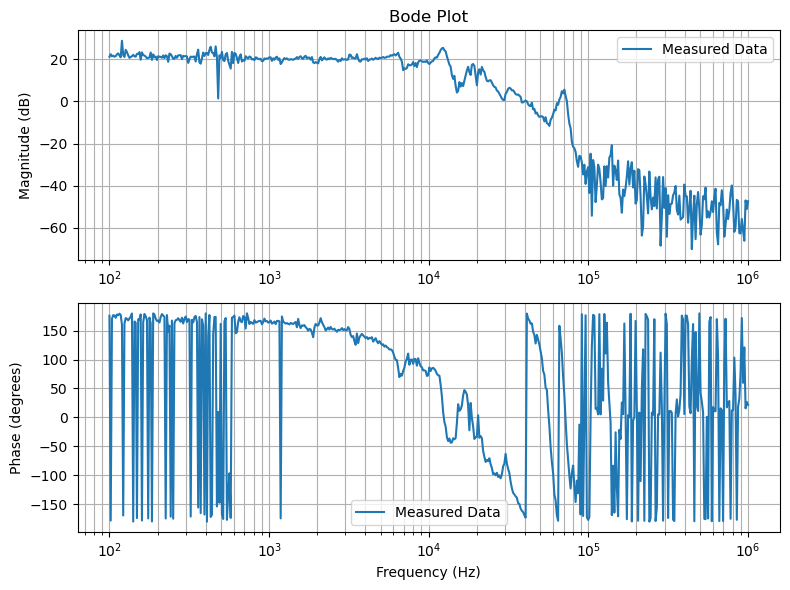
1) Take OFC TF. rawdata.png
2) Rescale the magnitude of the data so that it is 0 at low frequencies.
3) Invert it in complex form and choose the appropriate window for the filter. invertedandwindowed.png
4) Down sample the data to make the experimentally taken data smoother.
5) Fit the down sampled data to ZPK format. ZPKfit.png
6) Convert your ZPK curve into second order sections.
7) Write it to a text file in the format the moku wants. output.txt
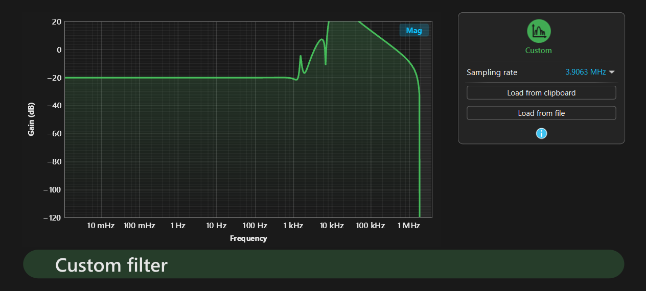
success.png (I moved it down 20 dB so you can see the shape at high frequencies. This is done with the leading single digit on its own line in the text file.)
Some notes associated with this:
-The moku can only upload 4 SOS in this format as a custom filter. Limits the amount of shape we can add to our filter dramatically.
-We will upload this script to the log in a cleaner format but for now here it is piezoTF_calculation.ipynb. Its really messy though, we'll update with a cleaner version soon.
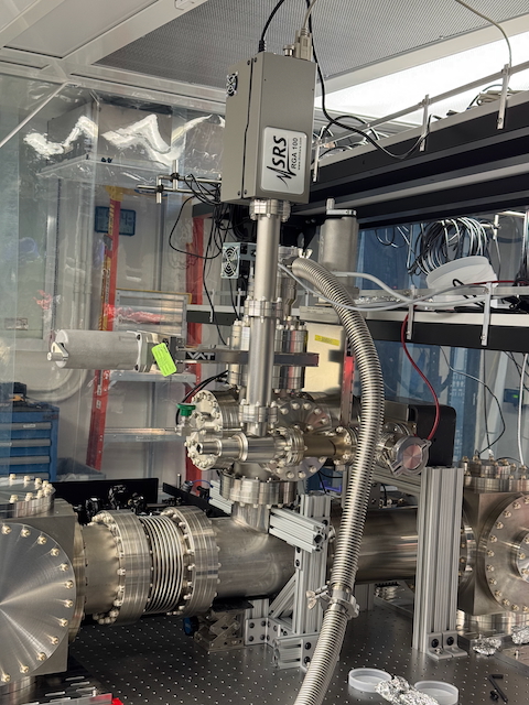
Here is a cleaner version of the same script.
Data for the script.
I downloaded and briefly set up some software to talk to the turbo pump and pressure gauge on the LFC. I took off the interlock to prevent the turbo from accidentally turning on.
I cleaned 15 Nitronic 60 1/4-20 1/4 long helicoils and 4 of the 5 custom 1/4-100 bushings. I used the standard 1:30 simple Green:DI water, DI water, then isopropanol baths and sonication for 10 minutes each. I am currently baking them out at 200°C for 48 hours.
200°C reached at 2:40 PM.
[Jeff, Daniel]
I connected the Stanford Research Systems Residual Gas Analyzer 100 (SRS 100) RS232 cable (9 pin D-Sub) to a RS232 (male) to USB-A (male) adapter and plugged it into the USB hub in the mobile clean room. I also connected the same adapter from the turbo controller to the hub. I turned on the RGA and took some spectra around 3:30 today. I've attached the graphs from the data. The y-axis is Torr. The total pressure is the sum of the partial pressures; these graphs imply a pressure of around 1E-5 Torr, even though the Agilent pressure gauge had a reading around 1E-7 Torr, two orders of magnitude different. Jeff and I came in around 11 PM tonight and took another RGA reading; H2 and N2 levels were higher than at 3 PM, up to 3E-5 Torr. We then found out the pressure is 1E-3 Torr on the Agilent pressure gauge and the ion pump was off. I don't know if the ion pump going off is a cause or an effect of the high pressure. If the 6E-10 Torr/s rate of rise measurement is accurate, then the pressure after ~12 hours would be ~3E-5 Torr. This seems to indicate the high pressure caused the ion pump to go off. If the helium from the helium leak check were in the system, it would be easily visibile with the RGA (and shouldn't cause such a huge pressure rise). The up-to-air valve and the gate valve to the turbo pump were closed and tight.
If the pressure is this high, this explains the RGA measurments being so high (it's not rated above 1E-4 Torr, so a little discrepancy there makes sense). There is a big mystery for why the pressure is 1.2E-3 Torr after being stable for days. To test the agilent pressure gauge, I rotated and moved the magnet's z-axis (it's a cylinder and on another cylinder). This lowered the pressure to ~7E-4 Torr, half as low. A factor of 2 in pressure isn't a big deal for these issues.
The H2 levels on the RGA also seem quite high.
Even though everything is off, the presssure went down to 2.8E-4. I don't have a good explanation. Maybe there are E&M fields from the RGA or ion pump that affect the pressure gauge's reading.
See this post for a partial explanation for why the pressure rose to 1E-3 Torr and stabalized there.
[Jeff, Daniel]
We attached the Infleqtion PICAS 2D Rb MOT Adapter Plate to a 2.75" CF Bellows with 1.25" long 1/4-28 screws and no washers. 0.875" long screws weren't quite long enough. The gasket was initially incorrectly seated on the knife edges; putting the curved edge on the bellows seemed to help when I tried again with a new gasket. I tightened the bolts to 14 Nm, the standard for 2.75" CF thru flanges, and made steel to steel contact all around.
I cleaned the 6082 aluminum parts that hold the mirror and piezo to lock in vacuum cavities/interferometers. I used the standard 1:30 Simple Green:DI water, DI water, then isopropanol baths and sonication for 3 minutes each. I am currently baking them out at 120°C for 48 hours.
[Jeff, Ian, Daniel]
We vented the turbo/scroll system on the Laser Filter Cavity (LFC) by turning the knob on the turbo pump. There was a decent amount of air that came in, implying there is a good seal from the turbo to the outside world, even when the scroll and turbo are off. The gate valve was closed and we noticed no pressure increase in the main body of the LFC, implying the gate valve seal is good. We then vented the main body of the LFC with the up-to-air valve. A little turn increased the pressure from 1E-5 Torr to 1 Torr, so one needs to be careful there. I turned the valve a bit more and the pressure slowly increased. Notable, there was a lot of gas sucked into the LFC even when the pressure gauge read "over pressure" (over 760 Torr). I therefore tried to play with the magnet on the pressure gauge once the LFC was fully vented to get the controller to display 760 Torr. Rotating it and moving its z-position didn't accomplish it.
We took off a CF 2.75" to KF50 adapter + a KF50 blank flange and added a 7" long 2.75" CF tube to the all metal angle valve (the latter of which was quite dirty on the flange outside the vacuum ). We needed this 7" long part so that the cup of the Stanford Reserach Systems Residual Gas Analyzer 100 (SRS RGA 100) had room to be inserted into the vacuum system (it needs ~3"). We then connected the SRS RGA to the tube and we tightened the bolts.
I opened up the gate valves and had previously opened the all metal angle valve to the RGA and shut the up-to-air valve and turned on the scroll pump. After 20 minutes, the pressure was 0.1 Torr like before, so I don't think fiddling with the magnet changed anything. I then turned on the turbo (still in soft start mode) around 0.08 Torr. The pressure and power drawn behaved like last time. 20 minutes after turning on the turbo, the pressure is 4.9E-6 Torr.
To use the RGA (and have the turbo controller, which reads out the pressure) talk to the computer, we need some RS232 (male) to USB-A (male) adapers. Ian found this which looks good.
The pressure was 9.8E-7 Torr at 7:42 PM.
The pressure was 1.5E-7 Torr at ~1:40 PM. I turned on the ion pump and the pressure rose to 1E-5 Torr before dropping to 3E-7 Torr in a few minutes with the turbo still on. The pressure topped out around 3.9E-7 Torr before dropping to 3.8E-7 Torr.
Yesterday, we had inserted the electronics control unit (ECU) onto the probe. I tightened the thumb screws to secure it. Since the pressure was 3.3E-7 Torr, I plugged in the ECU's power cord into the power strip. The green light turned on. I also installed the software onto the lab computer in the B111B control room. We don't yet have the RS232 to USB adapter to connect them, so I turned off the RGA and unplugged it.
[Jeff, Daniel]
We performed a rate of rise test for the Laser Filter Cavity (LFC) to determine the outgassing/leak rate (it's hard to experimentally differentiate without a bakeout or measurment over time). I turned off the Ion Pump and the pressure rose from 2.2E-7 Torr to 1.5E-6 Torr in 3 minutes from the ion pump releasing some gas. The pressure then rose linearly at 6E-10 Torr/s. Assuming the volume is ~33 liters, this gives a leak rate + outgassing of 2.7E-8 mbar*L/s. The surface area is around 1 m^2 = 1E4 cm^2. Assuming the leak rate is negligible, the desorption rate is 3E-12 L*mbar/(cm^2*s), which is excellent (almost unbelivable). There are calculations that can be made from this data to access the performance of the vacuum pumps. I might do that later. See below for the raw data and graphs.
Time (minutes) | Time (seconds) | Pressure (Torr) |
0 | 0 | 2.2E-07 |
0.666666667 | 40 | 7.5E-07 |
3 | 180 | 1.5E-06 |
3.5 | 210 | 1.6E-06 |
7.5 | 450 | 1.7E-06 |
8 | 480 | 1.8E-06 |
11 | 660 | 1.9E-06 |
18 | 1080 | 2.0E-06 |
20 | 1200 | 2.1E-06 |
24.5 | 1470 | 2.2E-06 |
32.5 | 1950 | 2.6E-06 |
35.7 | 2142 | 2.7E-06 |
38.25 | 2295 | 2.8E-06 |
I cleaned the top of the IFO Vacuum Cube and added a 10" to 6" CF Zero Length Reducer Flange. I then added a 6" CF 6 way cross (with a rotatable flange face down). I tightened the bolts so that the copper flange wasn't visible and there was steel to steel contact all around.
I moved a bunch of vacuum equipment from B150 to B111B for the igo cube: A 2.75" CF Tee, 4 way cross, angle valve, all metal angle valve, pressure gauge (down to ~1 mTorr) two 6" CF Gate valves, a small ion pump, and an ion pump controller. A bunch of other equipment was attached to what we needed, including two 8" to 6" CF reducer tees, 6" CF tubes, additional 2.75" angle valves.
I also moved an all metal angle valve into B111A for the RbQ chamber.