Daniel Grass - posted 15:05, Monday 19 February 2024 (11478)
10
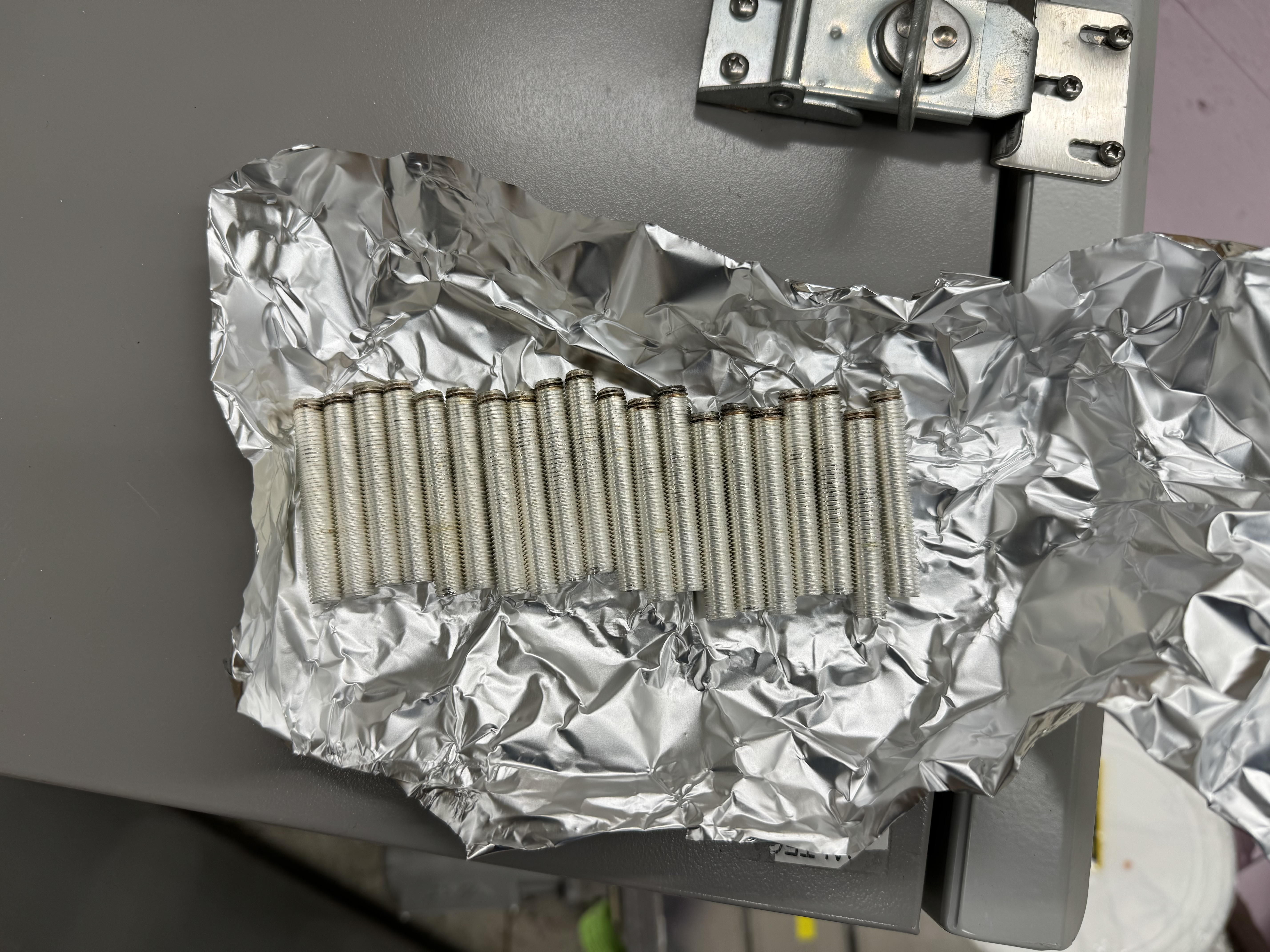
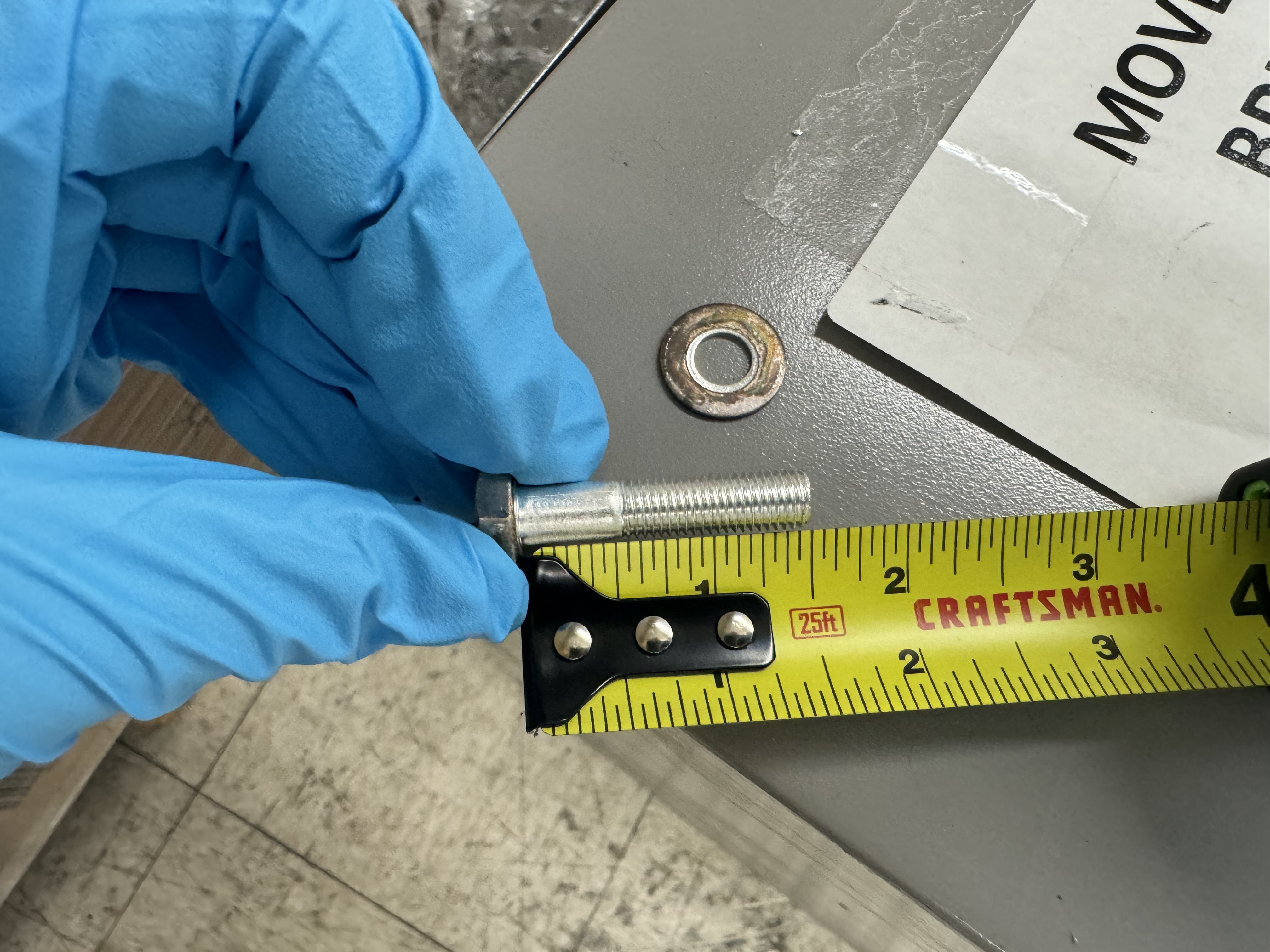
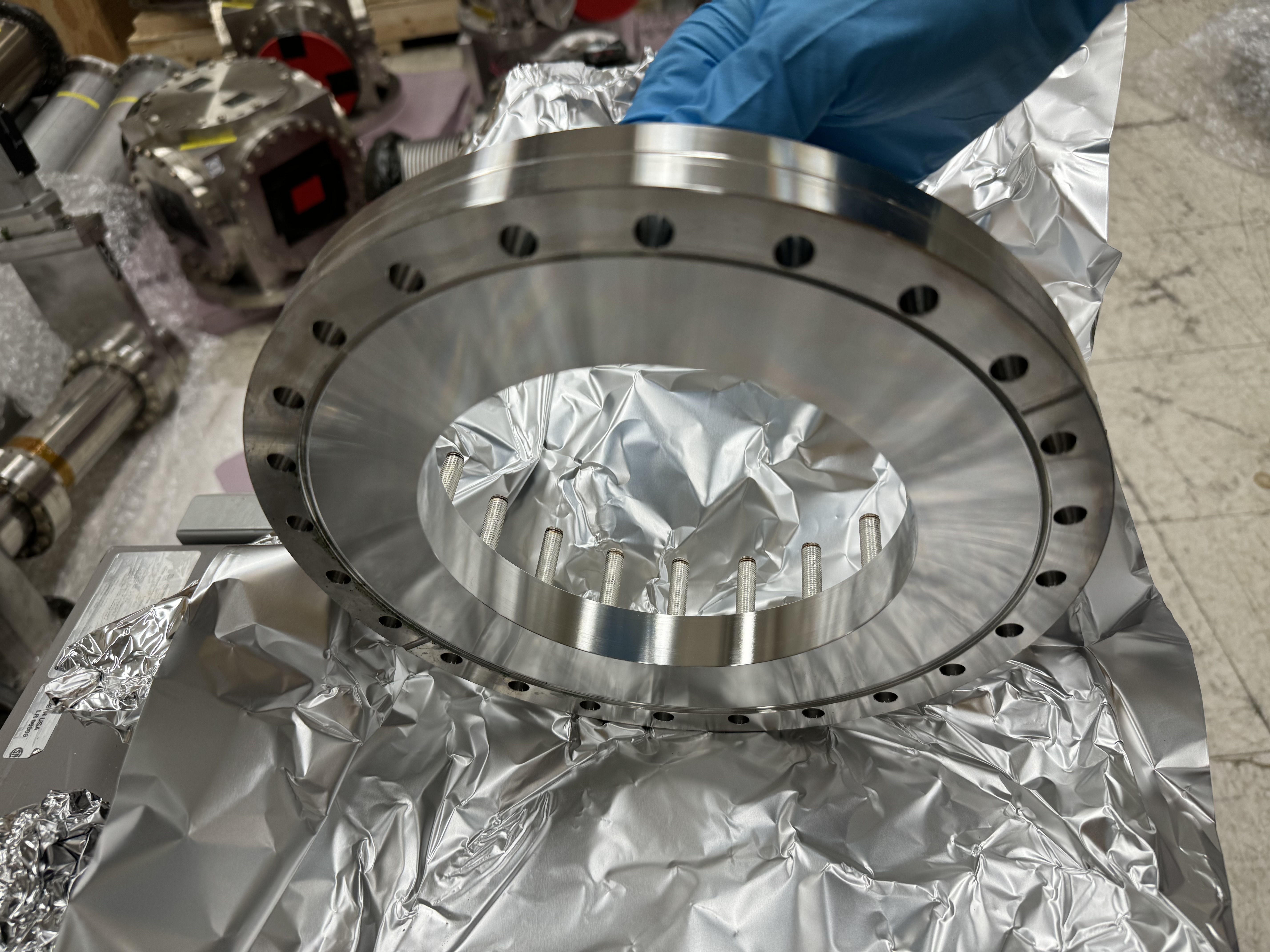
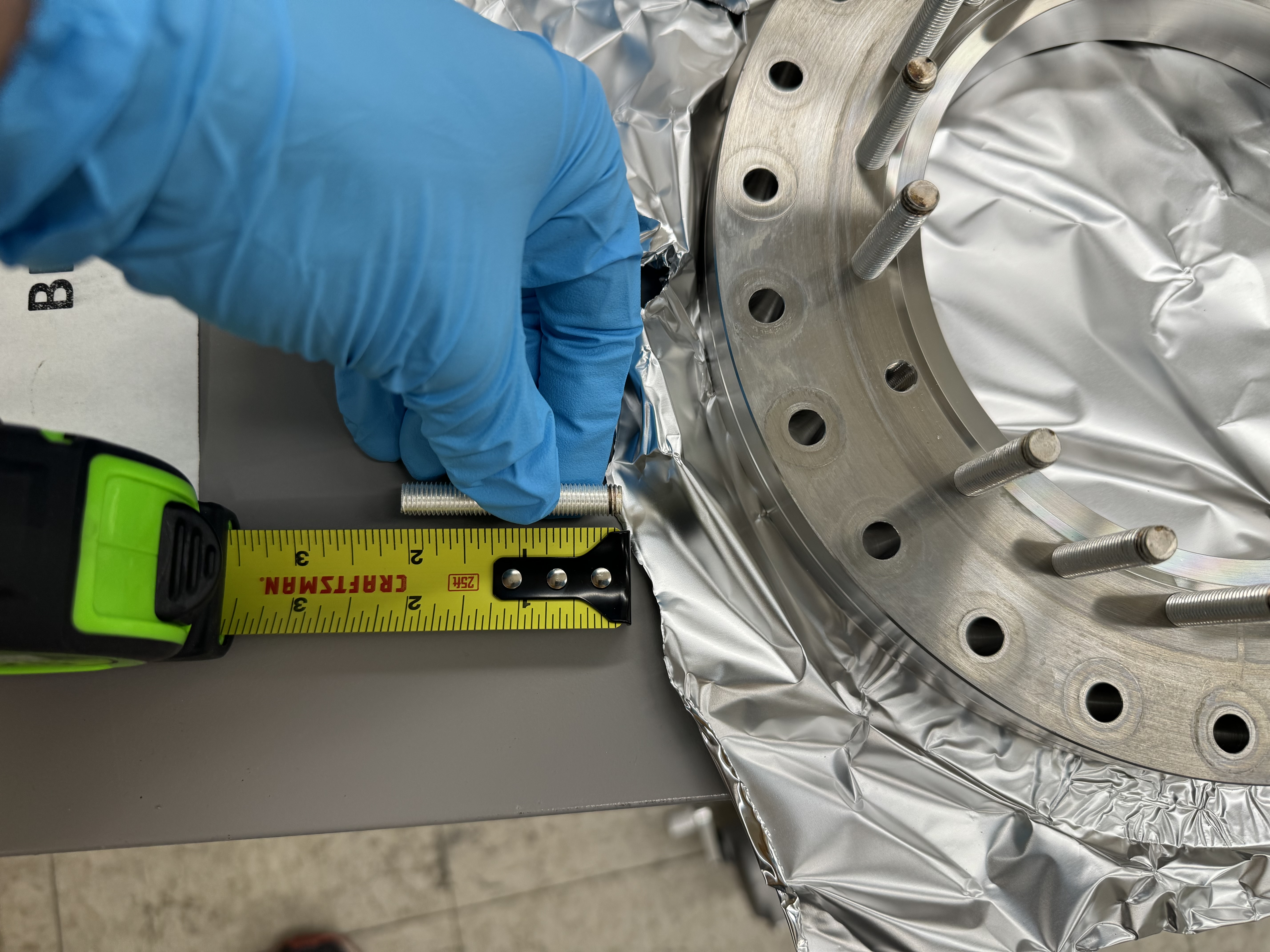
I removed the 2" long, 5/16-24 set screws from the 10" to 8" Flange Size Zero Length Reducer. The set screws do not have a hex drive (perhaps they are more accurately called studs), and ~16 of the 20 required pliers to remove. This caused a bit of silver plating to come off, but it was easily removed with an air duster. The ends of the screws furthest away from the flange were quite dirty and/or lost their silver coating. See attached photo.
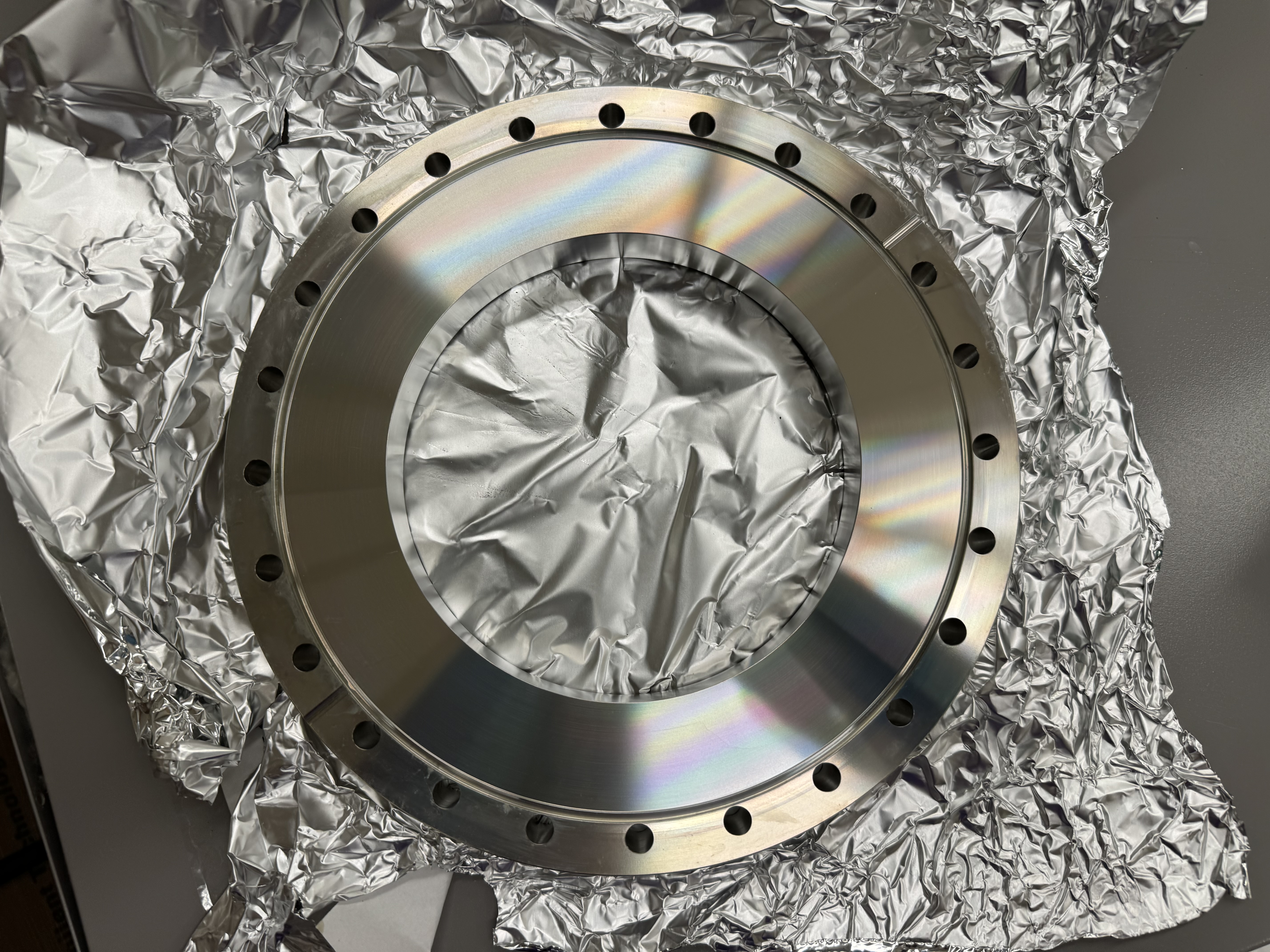
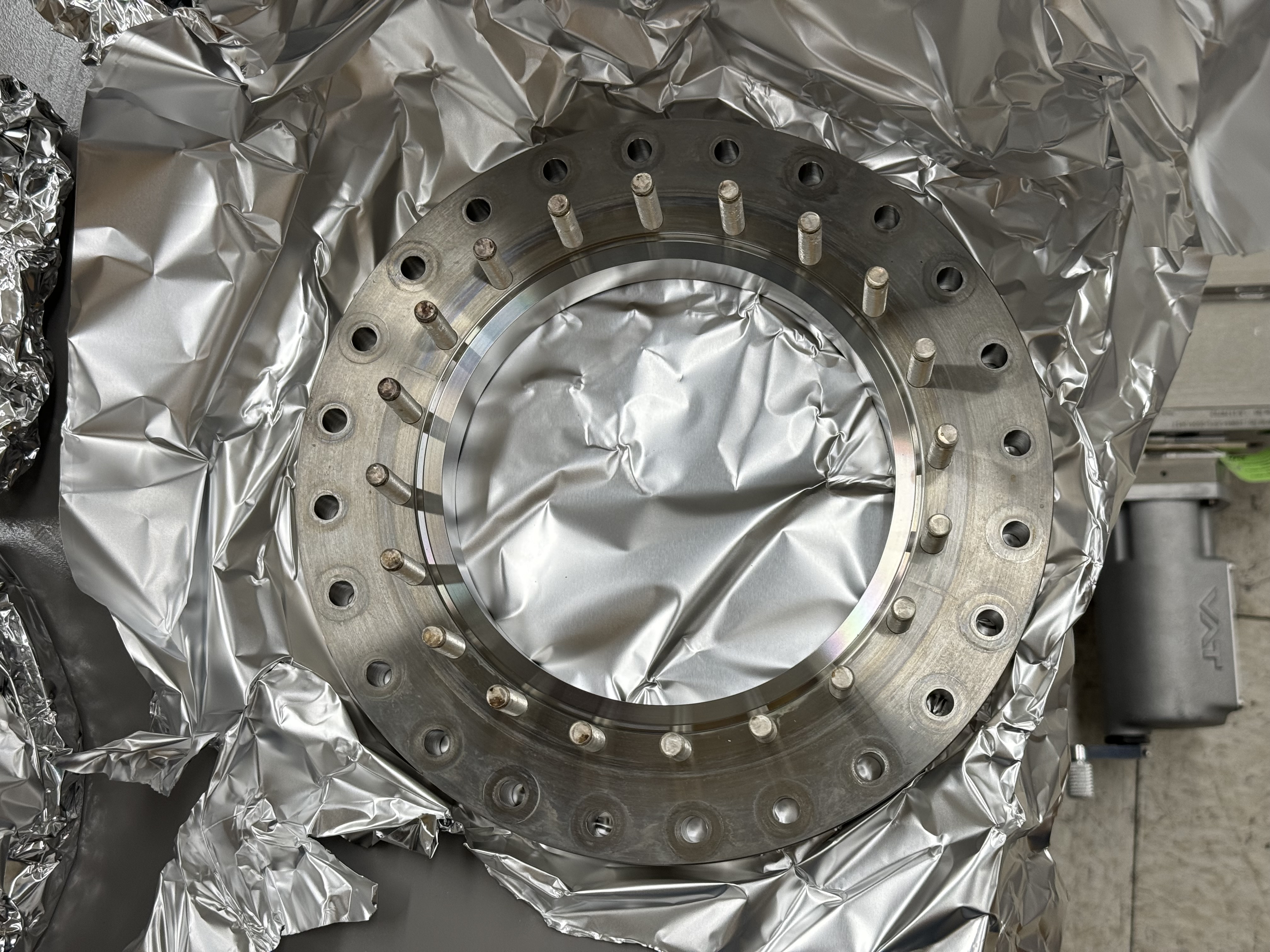
I then used isopropanol and Kim wipes to clean the non vacuum part of the reducer. Some gunk made it into the part where the copper gasket lies outside the knife edge. I cleaned this to the best of my abilities. See attached photo.
Images attached to this report