Displaying reports 881-900 of 1093.Go to page Start 41 42 43 44 45 46 47 48 49 End
Reports until 17:26, Thursday 18 January 2024
GQuEST Output Filter Cavities
Torrey Cullen - posted 17:26, Thursday 18 January 2024 - last comment - 07:07, Friday 19 January 2024(11423)
mystery resonance investigation

[Daniel, Mai ,Torrey]

The leading theory on the ~520 Hz resonance seen in the spectrum of the cavity error signal is some part of the flexture mount mirrors resonating. To test this theory we pushed on the mirror with viton to see if the resonance is damped/moved at all. Our initial test has a viton O ring pushing on M2 of the cavity only. We did this with and without pushing on the mirror, results seen here image.png. We are skeptical of these results and tomorrow will:

a) repeat this test several times. It is time consuming as the force on the cavity mirrors misaligns the cavity.

b) instead of relying on the ambient noise of the room to ring up, use phones to drive at say 520 +/- 20 Hz at constant locations between tests.

Images attached to this report
Comments related to this report
Chris Stoughton - 07:07, Friday 19 January 2024 (11424)

Can you rig up something to do a swept sine of a speaker placed on the table?  This will probably be enought to drive the resonance.

When you "push with an o-ring" I think that will absorb energy from vibrational modes.  Is that correct?


Is it possible to have the entire cavity sit on viton?  A quick way to do this is to have a sheet of viton between the cavity and the table.  

We shipped out some of the "platforms" that were inside the Holometer vacuum systems.  These have recesses for viton balls so the platform is stable. I do not recall the cutoff frequencies of that system, but it eliminated our acoustic problems.

GQuEST Output Filter Cavities
Torrey Cullen - posted 15:24, Thursday 18 January 2024 (11422)
further cavity science

[Torrey, Lee, Daniel]

After some investigation we have found a mystery resonance around ~520 Hz. IMG_0015.png is the set up used to take a spectrum of the error signal and the control signal. As seen from mysteryresonance.png (blue is error, orange control) you can see a resonance peak at ~520. This exibits resonance type behavior, i.e. drive a sound at 520 Hz and measure the level of excitation and compare it to frequencies around this, say +/- 20 hz it is much reduced. 

Additionally we found some source of phase delay from our last post by taking a transfer function accros the piezo controller, as seen in IMG_0020.png. Lee mentioned it would be useful to create a filter that inverts this amplitude loss.

Images attached to this report
Non-image files attached to this report
General (GQuEST)
Chris Stoughton - posted 08:13, Thursday 18 January 2024 (11420)
RedPitaya analog_echo

The same sd card in a different RedPitaya and power supply works.  


Yellow is the input signal to the RedPitays.  Blue is the output, with offset register set to 100 mV.  The delay seems to be 100 ns.  The gain seems to be a bit more than 1.


So, we can read and write analog signals and control registers with pynq.


Images attached to this report
GQuEST General (GQuEST)
Daniel Grass - posted 17:17, Wednesday 17 January 2024 - last comment - 14:19, Thursday 18 January 2024(11418)
Power Distribution Sled Power Drift Test

[Torrey, Daniel]

We aligned light from the misc category into a fiber on the power distribution sled. Instead of the 5 axis mount, we used a simple 2 axis mirror mount. We also tuned up the alignment into the other 3 fibers to maximize the power. We measured the power going into the fiber and out of the fiber to see if and how it drifts over time. Potentially, the 5 axis mounts will drift more than the 2 axis mount.

Comments related to this report
Chris Stoughton - 07:09, Thursday 18 January 2024 (11419)

Can you say what the "misc category" means?  Thank you.

Torrey Cullen - 14:19, Thursday 18 January 2024 (11421)

Hey Chris. The power distribution sled was designed to have 4 paths, 3 of the paths being ear marked for the output filter cavity, laser filter cavity, and SHG sleds. This last path is just for miscellaneous needs. Its going into a fiber that can be piped to any point in the room where we might need an extra laser source.

Controls General
Chris Stoughton - posted 12:35, Wednesday 17 January 2024 (11417)
RedPItaya -- analog feedback

I built the example analog feedback from https://github.com/dspsandbox/Pynq-Redpitaya-125


On one RedPitaya board the firmare loads, but setting the offset value via pynq causes the board to freeze up.  Identical firmaware and test on a second board succeeds.  Now will diagnose the "bad" board.  First suspect is the power supply.

Controls General (GQuEST)
Lee McCuller - posted 09:11, Tuesday 16 January 2024 - last comment - 23:01, Wednesday 20 November 2024(11413)
Filter cavity control

[Lee, Torrey, Daniel]

On Friday, we adjusted the loop shaping on the filter cavity to try and make the lock better. With a 1/f loop, it will lock, but goes between flickering out of lock, to oscillating as the gain is increased.

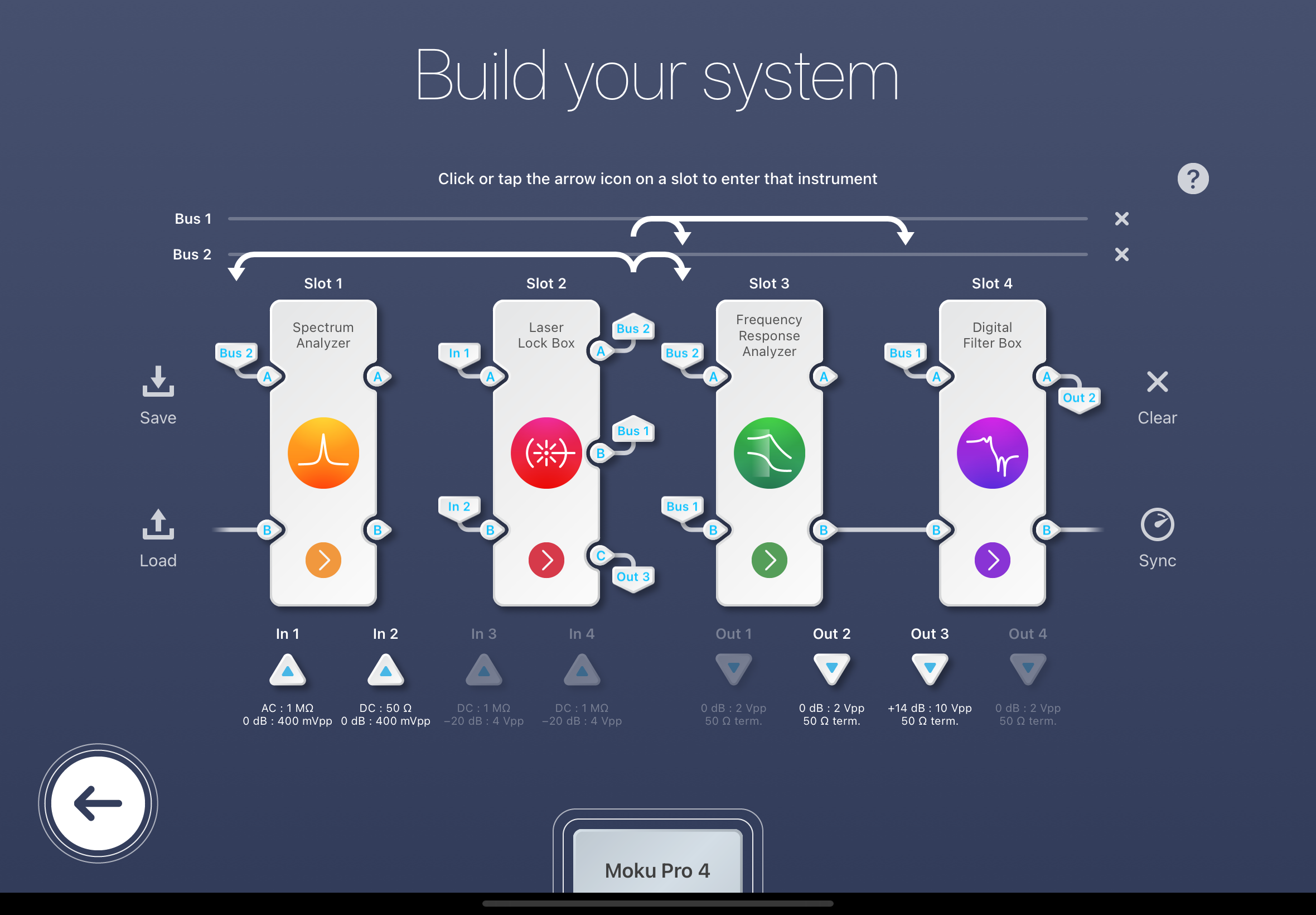
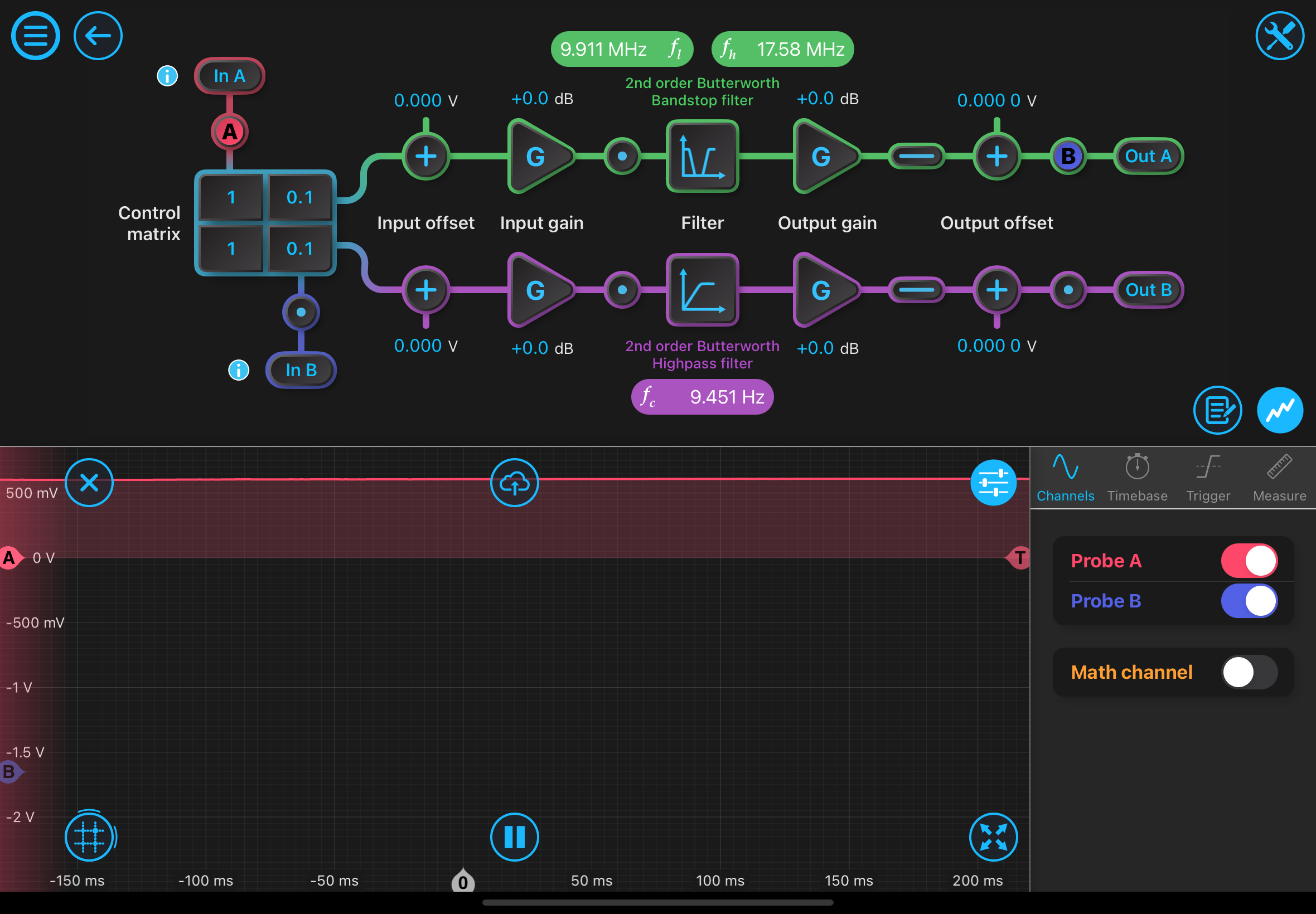
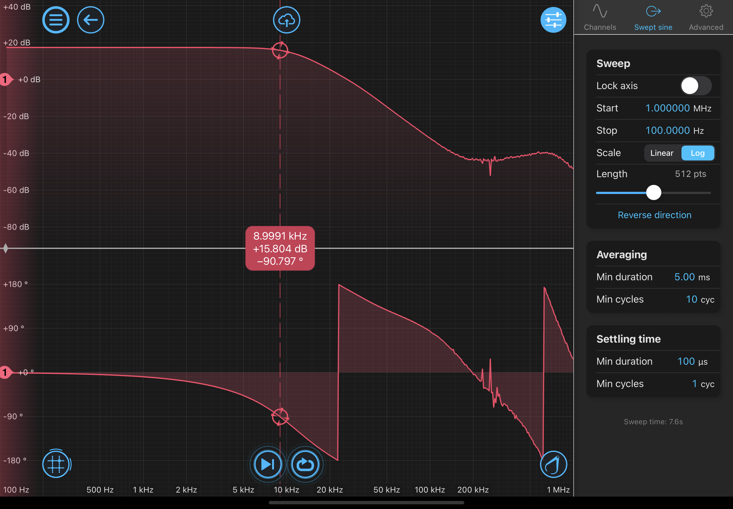
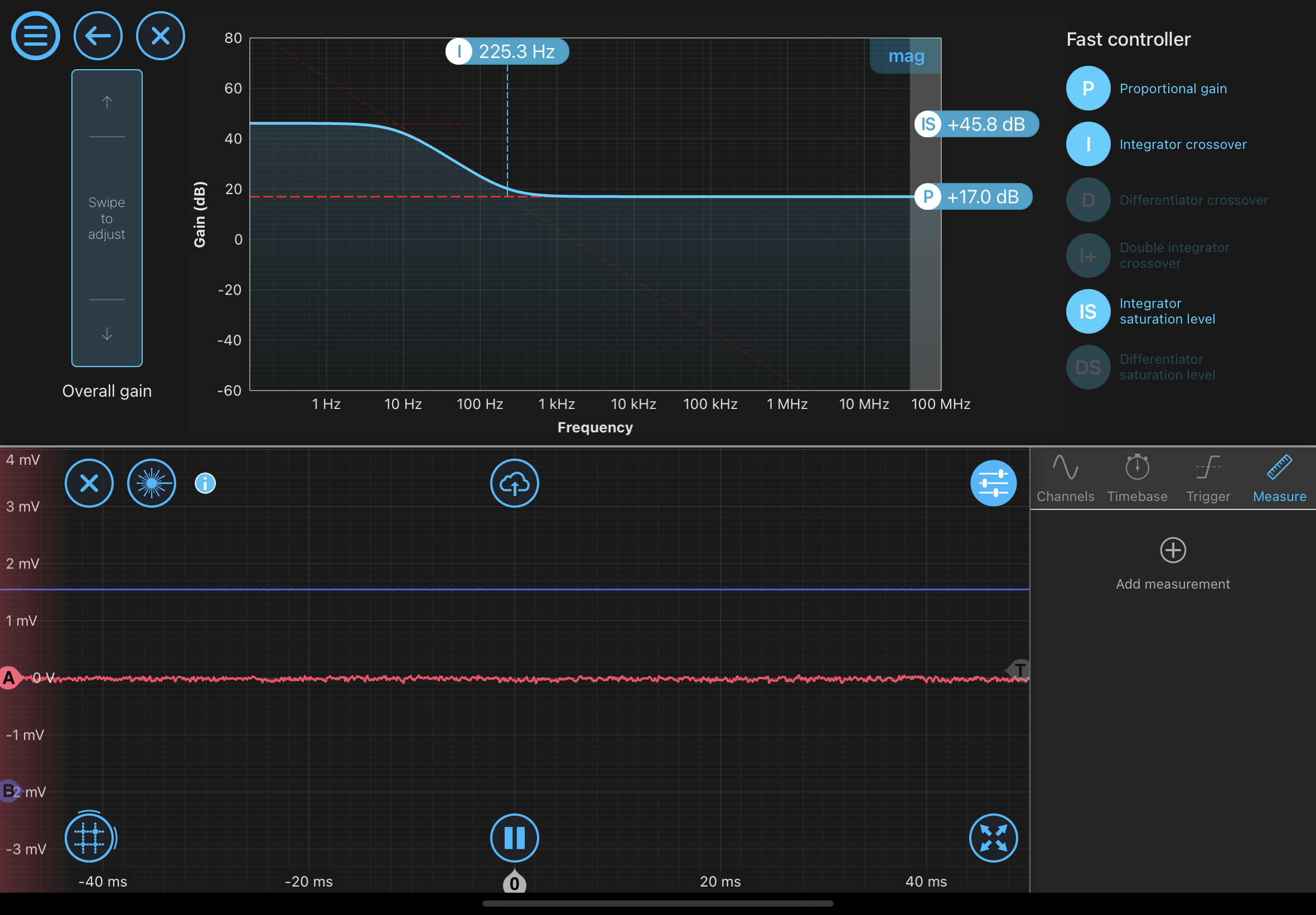
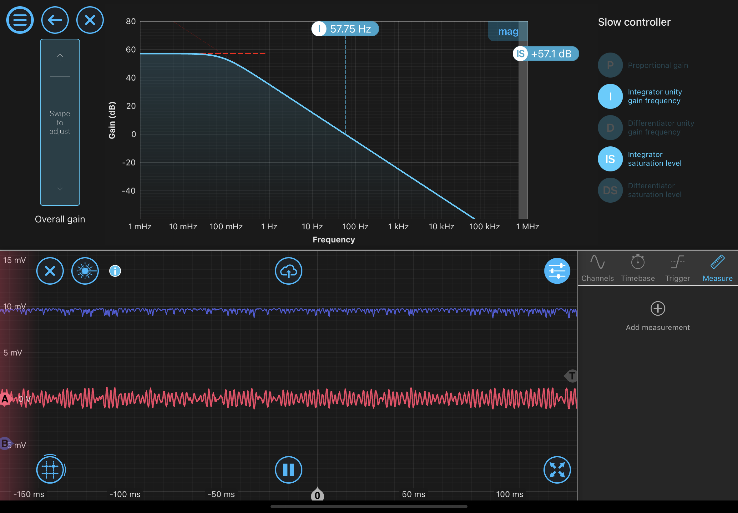
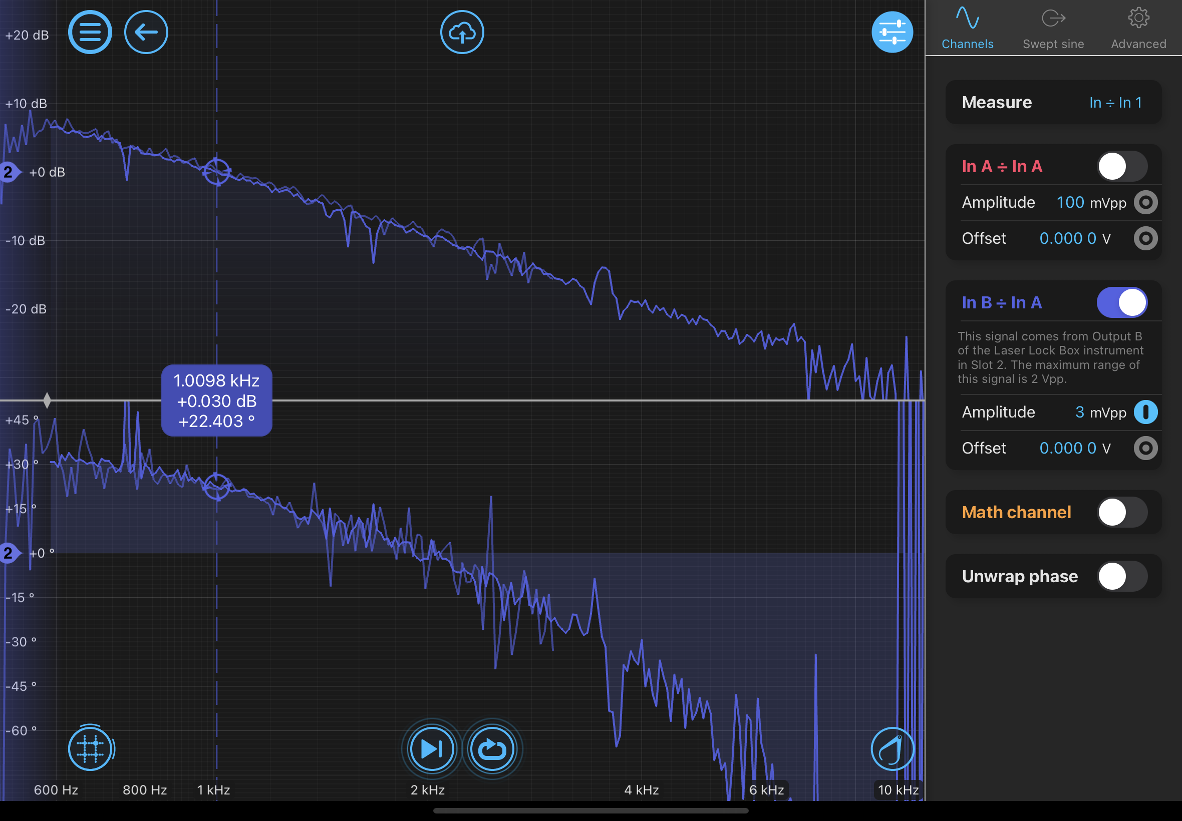
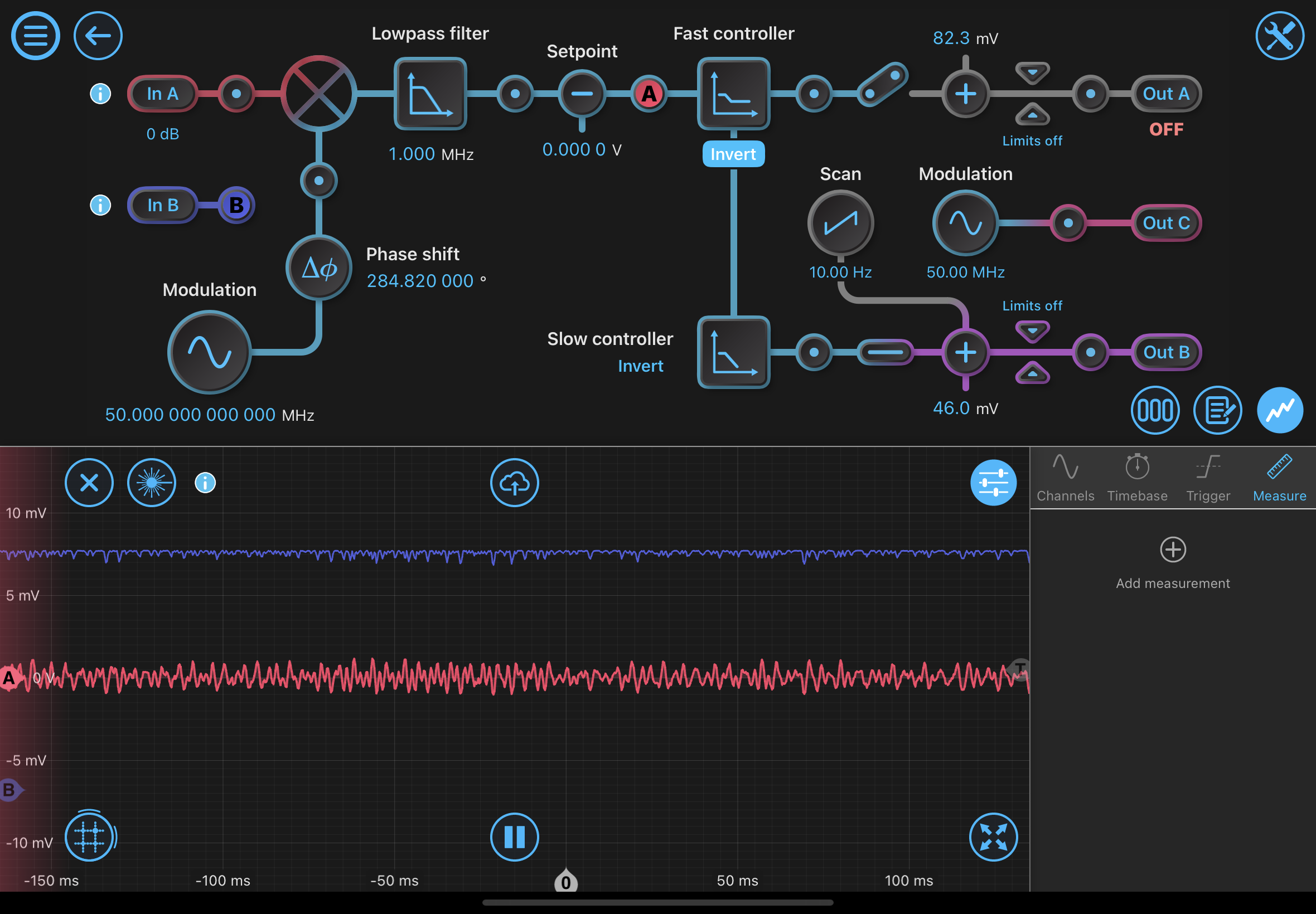
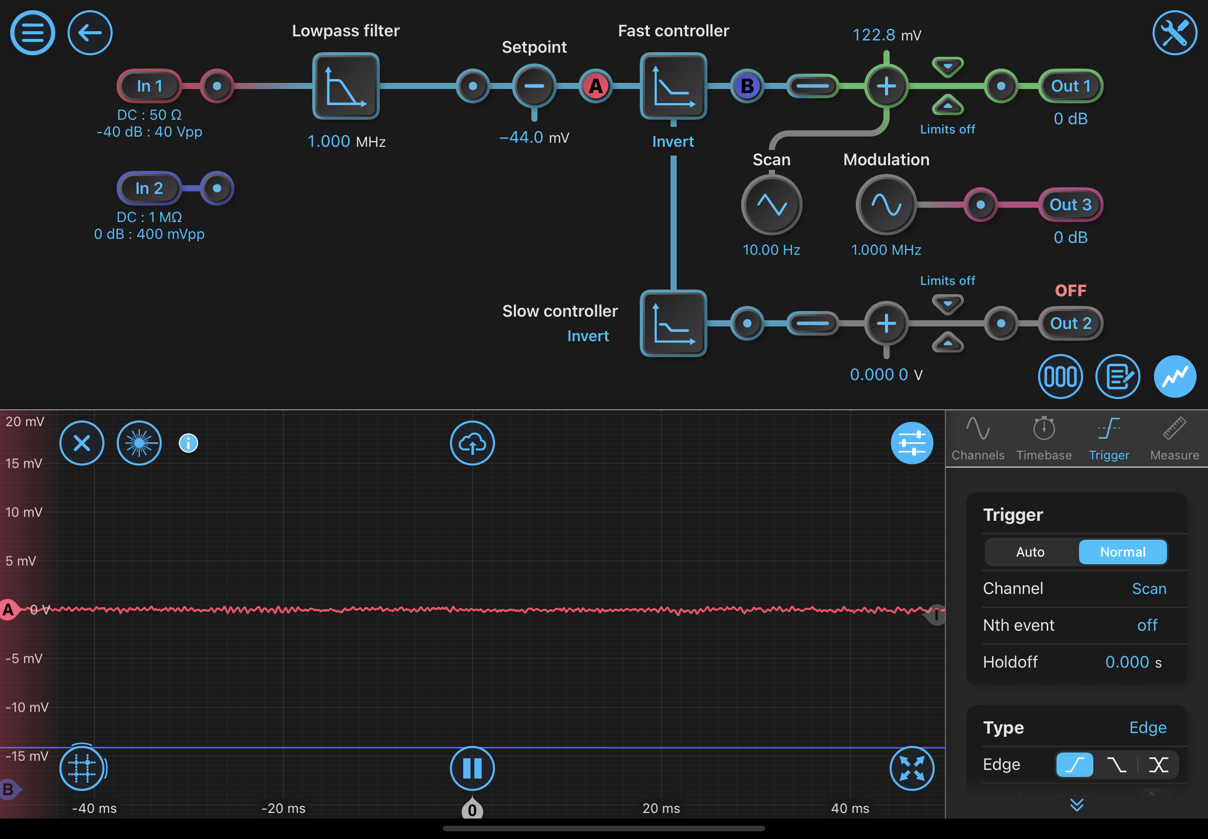
The new shaping uses the "slow" output of the "laser lock box." It shapes the fast output to have a 10Hz - 200Hz boost (pole - zero), giving 20x gain at low frequencies. The overall 1/f is then put at 1Hz in the slow path. We are able to get a UGF of 1kHz, with 30-40deg remaining. We lose 90deg by 2kHz from either the actuator or the Moku, so 1kHz is around the max UGF we can currently get.

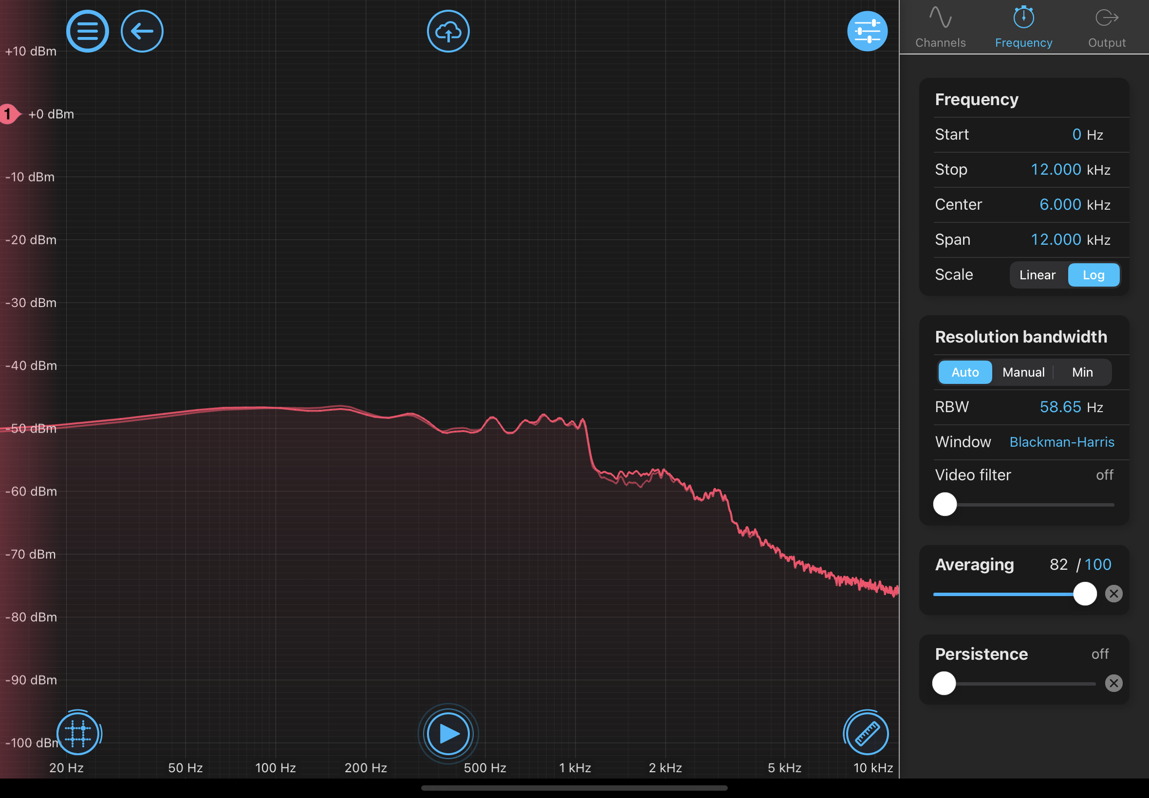
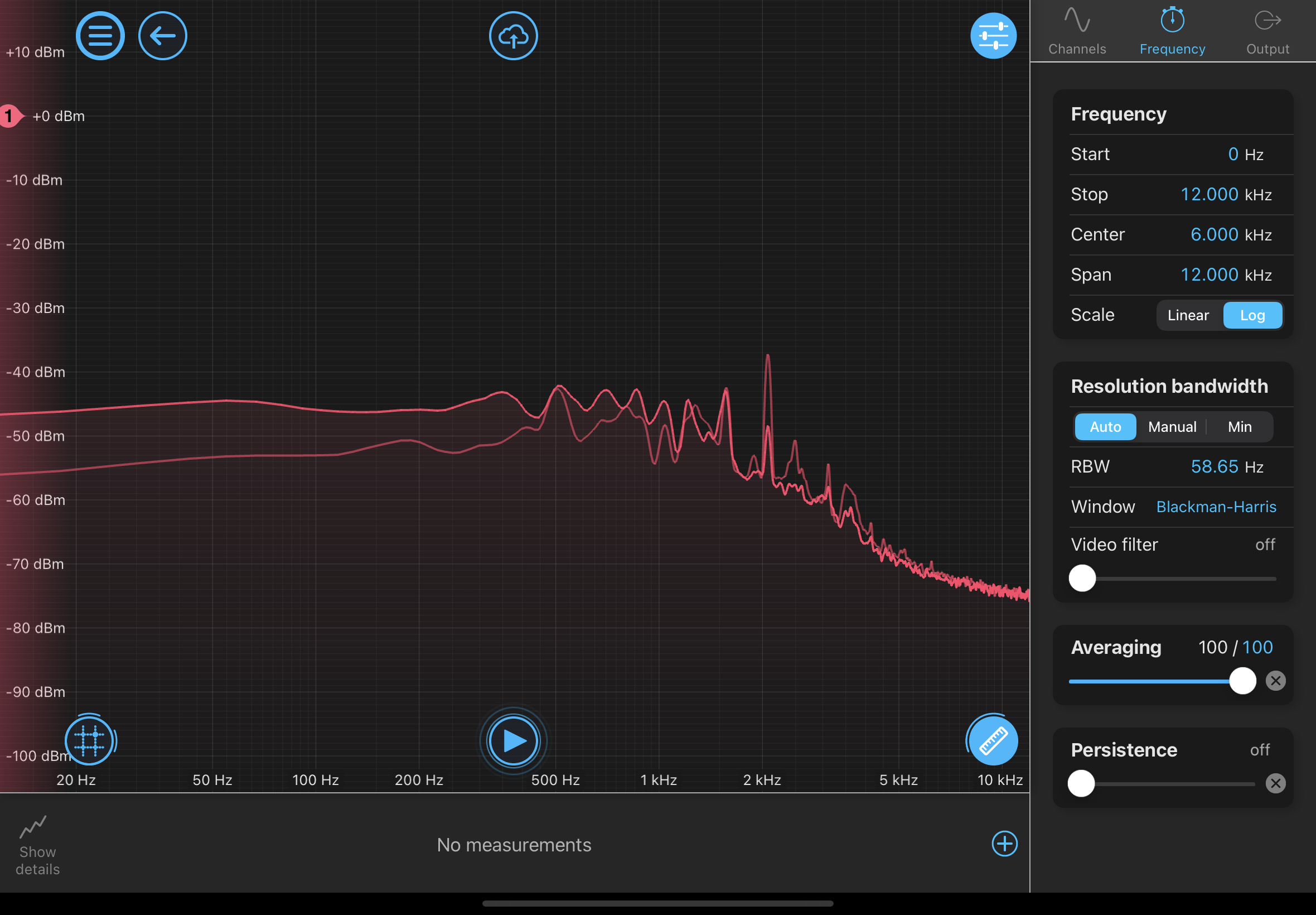
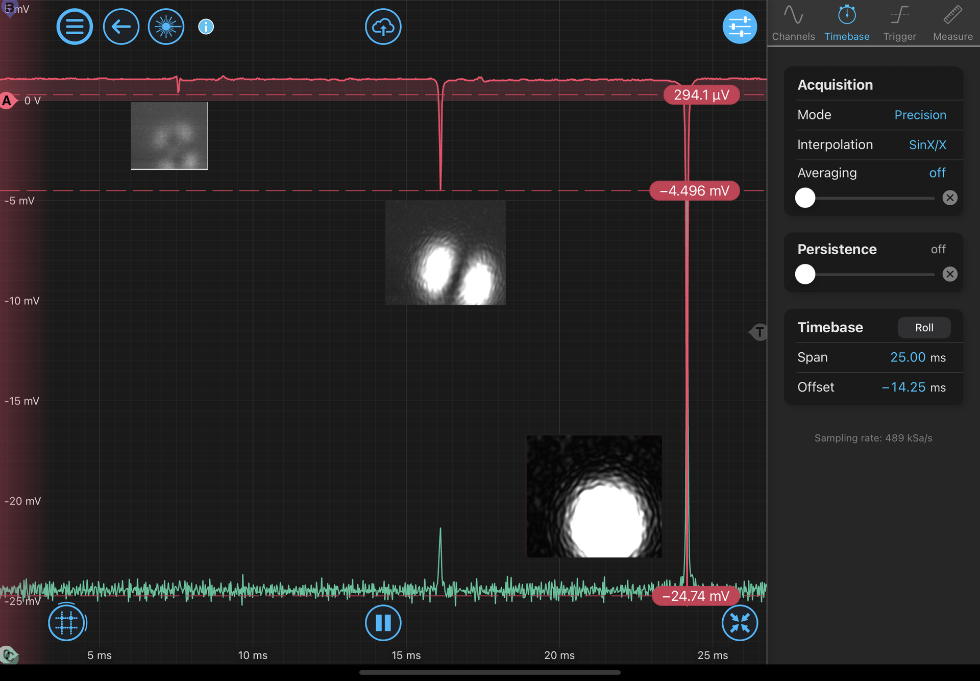
Even with that loop, we get dropouts while talking loudly or while the fans are on. Problematic. That mean the loop can supress the peak length noise below 1.5um / 2  / (2 * finesse). Our current input coupler is 1%, so our finesse is around 2pi / 0.01 = 600 (it might be as low as 300, depending on the losses in the cavity). So our peaks/RMS are around 0.5nm - 1nm of noise.


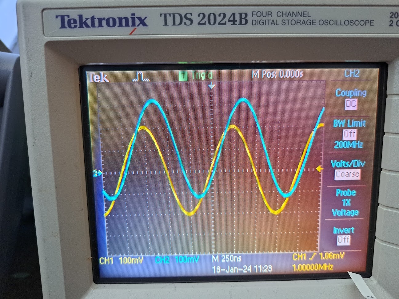
+1 to the piezo transfer teams. both 11380 and 11373 have the transfer function data along with the plots. It looks like all of the phase we are losing in the cavity lock is from the piezo (though could still be from Moku). We'll need to fit and at least slightly invert this actuator transfer function to make a loop above 1kHz UGF. The fit can help tell us how much of the phase is from the piezo roll-off.

We are going to need it - the current loop & cavity  has marginally too much noise, with an RMS around the linewidth. That is going to be a problem once we increase the finesse of the cavity. So we'll need to reduce the noise and/or improve the loop a respectable amount.

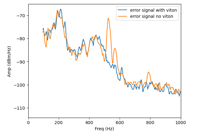
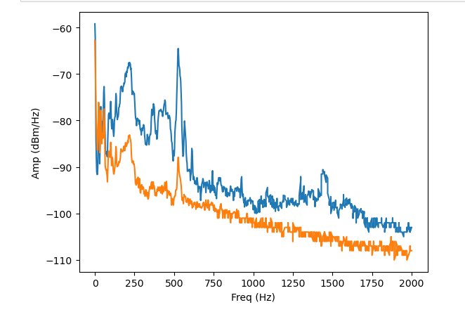
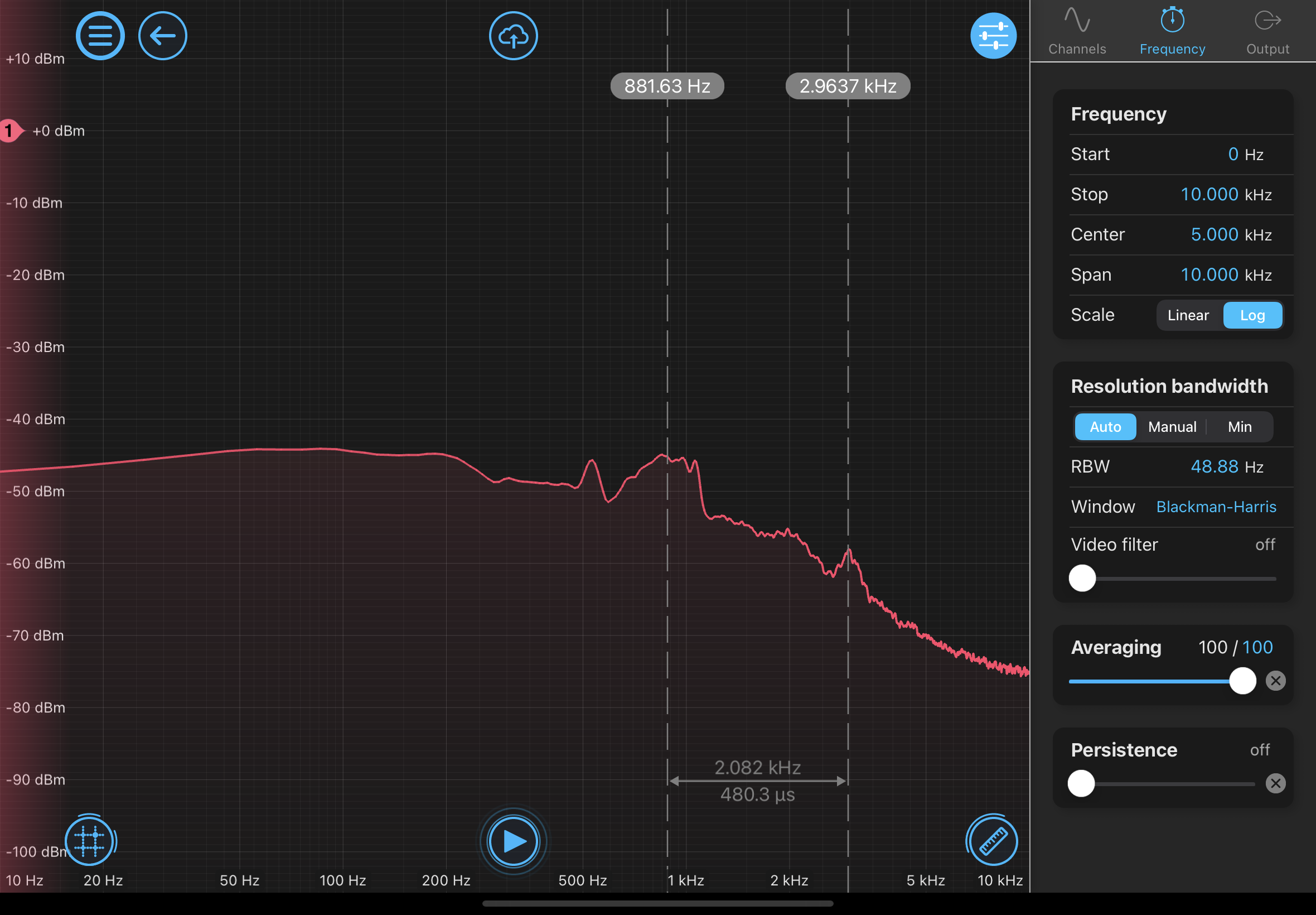
our voices are driving 100-300Hz, so we need gain there. If we can get the UGF up as high as 3kHz, then we should also be able to move the boosts up to 600Hz or so. That should give 9x more loop gain and cover much of the need.

options:

frequency lock - good for acquiring and transitioning to aggressive lock, but not an option for operating the experiment

optimal control - we can determine how good we can do with what we have

fitting/inverting actuator - probably needed to get UGF higher. May vary with time in bad ways

sound attenuation or active noise cancellation - may be possible and should look into engineering this.


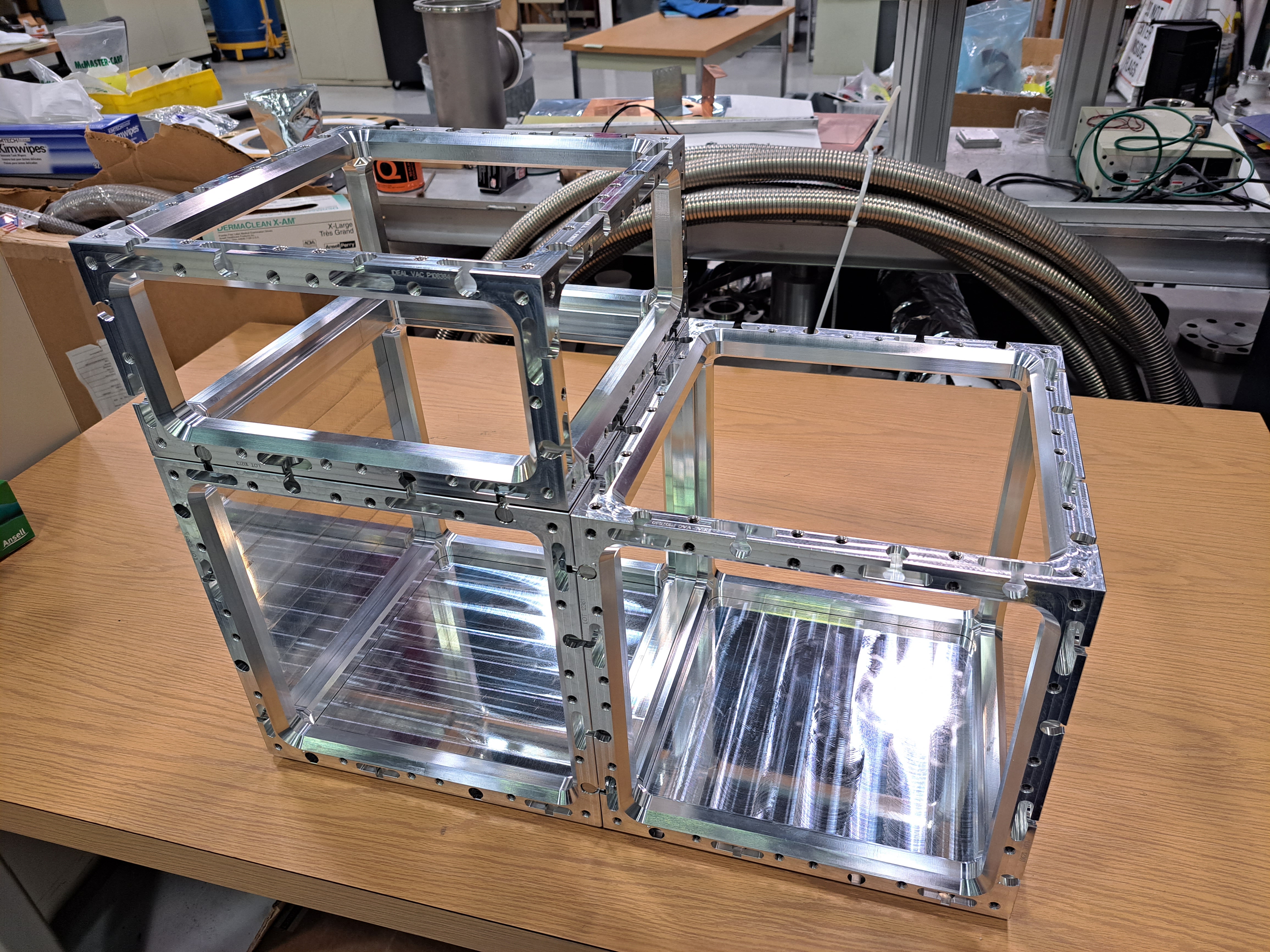
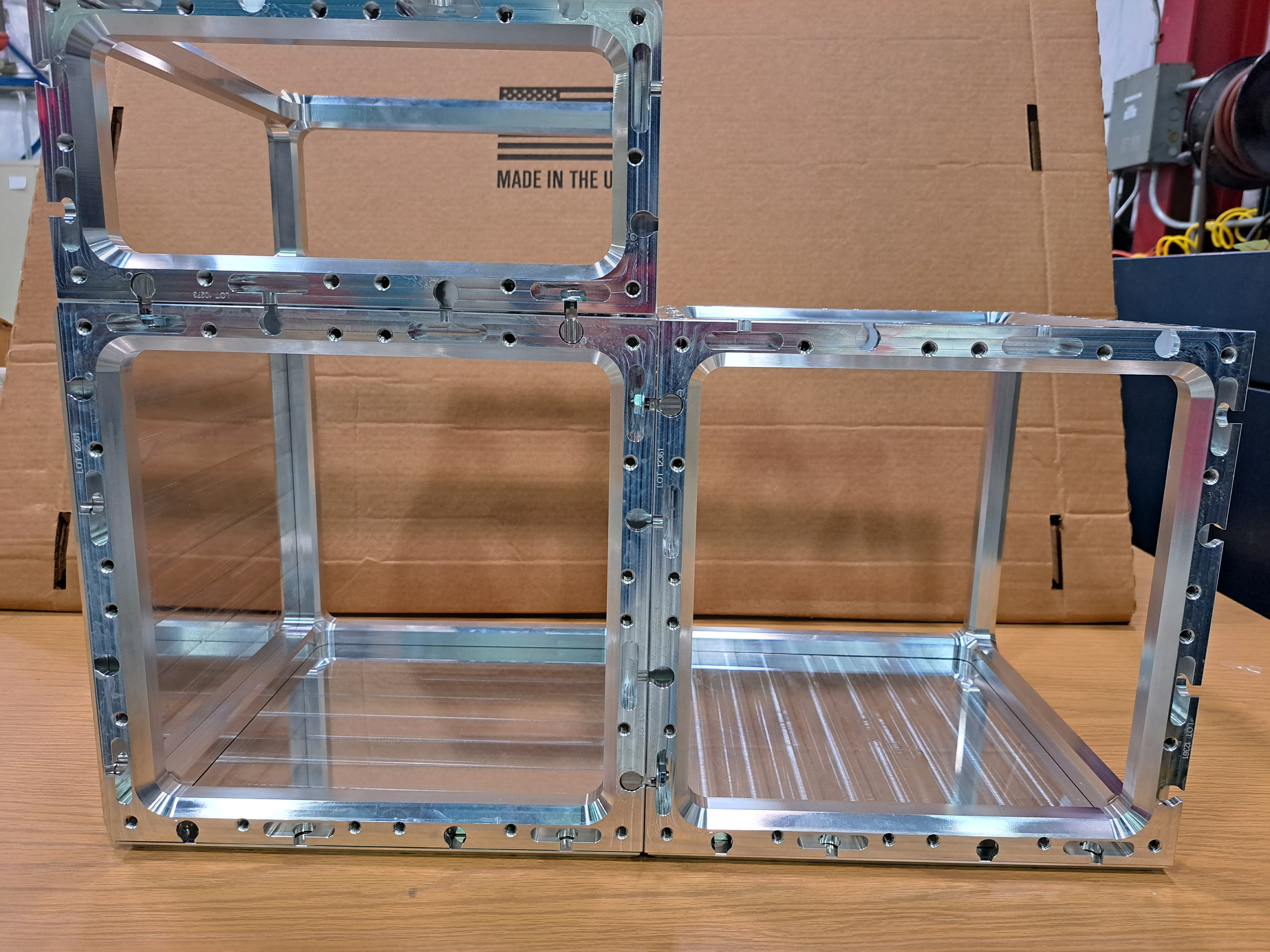
We should determine if the sound driving is from pushing the mirrors or from the index fluctuation as the pressure modulates. 11290 has calculations about the pressure pushing on a 1kg mass. My worry is that the small alignment adjust set-screws in the MKS flexture mounts are fairly compliant. Could sound drive them 1nm?
My guess is that the light going through 2m of air is the culprit.

The sound pressure of 40dB should be around 2000uP. Air pressure is 101kPa. The index of air is 1.000293

2m / (1.000293**2) * 2000e-6Pa / 101kPa * (1.000293 - 1) = 1.2e-11m

So that is a little small, but if our sound is at 80db, which would be quite loud, then it would be enough to cause this.

For the mirror motion, the mirror mounts are about 1.5in square. On the pressure level that is

(.0254m * 1.5)**2 * 2000e-6Pa = 3e-6N

of the mirror+panel is about 35g (very rough estimate). For a free mass motion that is

1 / ((2 * np.pi * 100Hz)**2 * 0.03534291735288516kg) * 3e-6N = 2e-10m which is getting in the ballpark with 60db of noise rather than 40db. The mirrors aren't free though.

and now I'm curious how that is against the spring constant of the tiny screw.

Comments related to this report
Torrey Cullen - 10:49, Tuesday 16 January 2024 (11414)

Supplement to Lee's post:

1) IMG_0005.png is the scheme used to achieve lock in multi-instrument mode.

2) IMG_0004.png is the closed loop gain while the cavity is locked. Note the UGF of ~1kHz as Lee mentioned.

3) IMG_0009.png is the slow controller loop.

4) IMG_0008.pngis a spectrum for f<10kHz. Note the resonance at ~3kHz. This may be the culprit and will be investigated.

5) IMG_0007.png is the fast controller loop just being used as a low frequency boost.

6) IMG_0010(1).png is the overall structure of the laser lock box as a reference for people that build this system in the future.

Images attached to this comment
Torrey Cullen - 11:28, Tuesday 16 January 2024 (11415)

Quick test to see if the air theory is likely. IMG_0011.png is cavity locked, fans off, no noise emitting as a control. IMG_0014.png is cavity locked, emitting a 1kHz sound from my phone about 1.5 meters away from the cavity with the lid off (reference trace) and lid on (active measurement). Noise is definitely muted. Air theory seems plausible.

Images attached to this comment
Daniel Grass - 14:10, Tuesday 16 January 2024 (11416)

Flexure Mount spring constant: E*A/L = 200 GPA * pi * 0.035 in ^2 / 0.1 in = 2*10^8 N/m

Resonant frequency: 75 kHz

RMS displacement: 2 * 10^-14 m for 40 dB of sound

Daniel Grass - 23:01, Wednesday 20 November 2024 (12007)

The small piece of metal that flexes on this mount is 0.020" thick and 1.5" long according to SolidWorks (this seems about right experimentally). This is a cross section 10x of the screw, so this also doesn't explain the acoustic pick-up.

Equipment General
Daniel Grass - posted 11:45, Wednesday 10 January 2024 (11411)
Newport 10D20DM.8 (1550 nm HR mirror) reflectivity of 775 nm light

[Torrey, Daniel]

We measured the reflectivity of 775 nm light on the Newport 10D20DM.8 (1550 nm HR mirror). At a 45° AOI, there is roughly a 40-50% reflection. +/- around 5° away from 45°, the reflection drops off sharply. Thus, these mirrors cannot be used to make a bowtie cavity for 775 nm light.

Low AOI: 3% reflection, 70% "transmission" but definitely a lot of this is scattered light

45°: 40-50% reflection depending on polarization, ~40% "transmission" but definitely a lot of this is scattered light

SNSPD General
Chris Stoughton - posted 07:02, Tuesday 09 January 2024 (11410)
SNSPD Dewar taking shape

The frame is assembled.  Custom-machined parts for the walls and inside shields are on order.


Images attached to this report
GQuEST Output Filter Cavities (GQuEST)
Daniel Grass - posted 17:34, Monday 08 January 2024 - last comment - 00:31, Monday 19 February 2024(11409)
Bowtie Cavity Alignment Tools

I 3D printed two aligment tools that slide into the corners of the bowtie cavity. The beam should pass through all 4 holes. The diameters are tight, so probably not the best to use for lining up the reflected beam and instead just use for the incident beam.

Comments related to this report
Daniel Grass - 00:31, Monday 19 February 2024 (11473)

Attached is the part as a SolidWorks file and STP.

Non-image files attached to this comment
General (GQuEST)
Chris Stoughton - posted 14:32, Monday 08 January 2024 (11408)
RedPitaya -- pynq

Following instructions here:  GitHub - dspsandbox/Pynq-Redpitaya-125 leads to better results.  

Built a project from scratch in Vivado 2023.2 to control the LEDs.  Include the QICK procedures extracted to ip.py to instantiate drivers. 


GQuEST Output Filter Cavities
Torrey Cullen - posted 14:40, Friday 05 January 2024 - last comment - 11:34, Monday 08 January 2024(11406)
Filter Cavity lock

[Daniel, Lee, Torrey]

First filter cavity lock!

No REFL dips were found after alignment from the new mode matching solution. Lee suggested instead use the very sensitive SWIR cameras to check in transmission of M2. We first replaced M2 with a 50/50 beam splitter to roughly align the cavity and see the beam making a round trip. Scanning the piezo mirror (M3) allows us to see higher order modes flashing. We use the mirrors before the cavity to align and maximize the 0,0 mode. We then put the HR mirror back in the M2 position instead of the BS. The reason this wasn't done before is we thought the frosted backs of the mirrors in use might obscure the beam, but this was not the case. You can still see a beam through the frosted back. We used the laser lock box to control the cavity with the piezo mirror and achieve a fairly robust lock. 

Images attached to this report
Comments related to this report
Torrey Cullen - 11:34, Monday 08 January 2024 (11407)

Scanned the cavity to see what modes are present. 0,0 is the largest, looks like horizontal alignment can be improved.

Images attached to this comment
Controls General (GQuEST)
Chris Stoughton - posted 12:32, Friday 05 January 2024 (11404)
RedPitaya work

First steps to customize pyrpl on the RedPitaya. Does it compile?

Install Vivado 2015.4 on Windows laptop. Clone https://github.com/lneuhaus/pyrpl.git In the directory pyrpl/pyrpl/fpga run this command in windows power shell:

C:\Xilinx\Vivado\2015.4\bin\vivado.bat -nolog -nojournal -mode batch -source red_pitaya_vivado.tcl

This created the files:

/fpga/red_pitaya.bin

pyrpl/fpga/project/pyrpl.srcs/sources_1/bd/system/hw_handoff/system.hwh


Installed pynq on a RedPitaya following https://github.com/dspsandbox/Pynq-Redpitaya-125 Trying to load the bitfile gives this error:


File /usr/local/share/pynq-venv/lib/python3.10/site-packages/pynqmetadata/frontends/hwh_frontend.py:452, in HwhFrontend._resolve_subordinate_addressing(self) 450 for i in self._root.iter("MEMRANGE"): 451 if i.get("MEMTYPE") == "REGISTER" or i.get("MEMTYPE") == "MEMORY": --> 452 core = self.blocks[i.get("INSTANCE")] 453 port = core.ports[i.get("SLAVEBUSINTERFACE")] 454 if isinstance(port, SubordinatePort): KeyError: 'M_AXI_GP0'

GQuEST Output Filter Cavities
Torrey Cullen - posted 12:23, Friday 05 January 2024 (11405)
Modematching Success

I added a lens between the two EOMs to ensure no clipping on the second EOM. I then reprofiled and found a MM solution to put the waist of 600 um at M3 (3.003 m from colimator output) in the cavity. This has been implemented and measured to have an average beam waist and location of waist (average of x and y, beam is slightly astigmatic) of 599.5 um @ 2.97 m. This should more than suffice to see some amount of resonance in the cavity. The nextcloud server is currently down but "Profiling after l1 12072023.ipynb" has this data on the lab computer. Will also update the layout mockup when the server is back up.

Images attached to this report
Non-image files attached to this report
Displaying reports 881-900 of 1093.Go to page Start 41 42 43 44 45 46 47 48 49 End