Displaying reports 101-120 of 1093.Go to page Start 2 3 4 5 6 7 8 9 10 End
Reports until 20:06, Wednesday 02 April 2025
Electronics General
Jeffrey Wack - posted 20:06, Wednesday 02 April 2025 - last comment - 15:42, Monday 07 April 2025(12221)
Power supply for Thorlabs laser

I tried to power the ThorLabs ULN15TK with a UX4 EXCELSYS power supply. It seems as though we have the XgF/Xg8 powerMods installed, each with a max current draw of 3A, so I wired two modules together in parallel to surpass the 4A asked for by the laser.

Plugging in the laser results in a green power light and no status light, but the emission light does not turn on after hitting enable.

We should perhaps buy another DS12 to power the ULN15TK, but I remain confused as to why the other power supply did not work. It is providing the correct voltage, but perhaps wiring two modules in parallel does not increase the current supply as I expect?

The state of the lasers is that both lasers and the amplifier are off. The signs remain on.

Comments related to this report
Daniel Grass - 10:46, Thursday 03 April 2025 (12222)

Laser seeder and amplifier are back on

Jeffrey Wack - 15:42, Monday 07 April 2025 (12227)

The new DS12 arrived in the mail. After using it to power the ThorLabs laser, we found that the 900Hz noise is present, but at a much smaller magnitude compared to the old supply.

Images attached to this comment
Electronics General (GQuEST)
Alex Ramirez - posted 18:53, Wednesday 02 April 2025 (12220)
PCBs for Dewar Thermometry

I have assembled and soldered the Thermometry PCBs to be mounted into the Dewar for initial pump-down tests. These PCBs were soldered in the vent hood in the chem room with lead-based solder and acuu glass flux that is vacuum compatible.

Upon finishing the boards, they were then soaked in isopropyl alcohol and sonically cleaned for 5 minutes (as directed on the accu glass website). 

Please see the last photos for side-by-side comparison of post soldering and post-sonicating.
 

Images attached to this report
GQuEST Output Filter Cavities
Torrey Cullen - posted 17:16, Wednesday 02 April 2025 (12217)
PDH setup for aux 1550 path to filter cavity 2

[Jeff, Torrey]

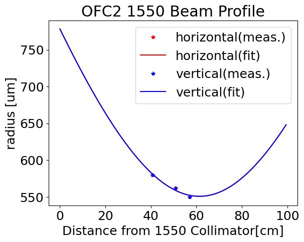
We setup a fiber EOM and a REFL PD to set up a PDH lock on the auxillary 1550 path to the second filter cavity. This will give consistent 1550 light leaving filter cavity 2 in order align and mode match into filter cavity 3.

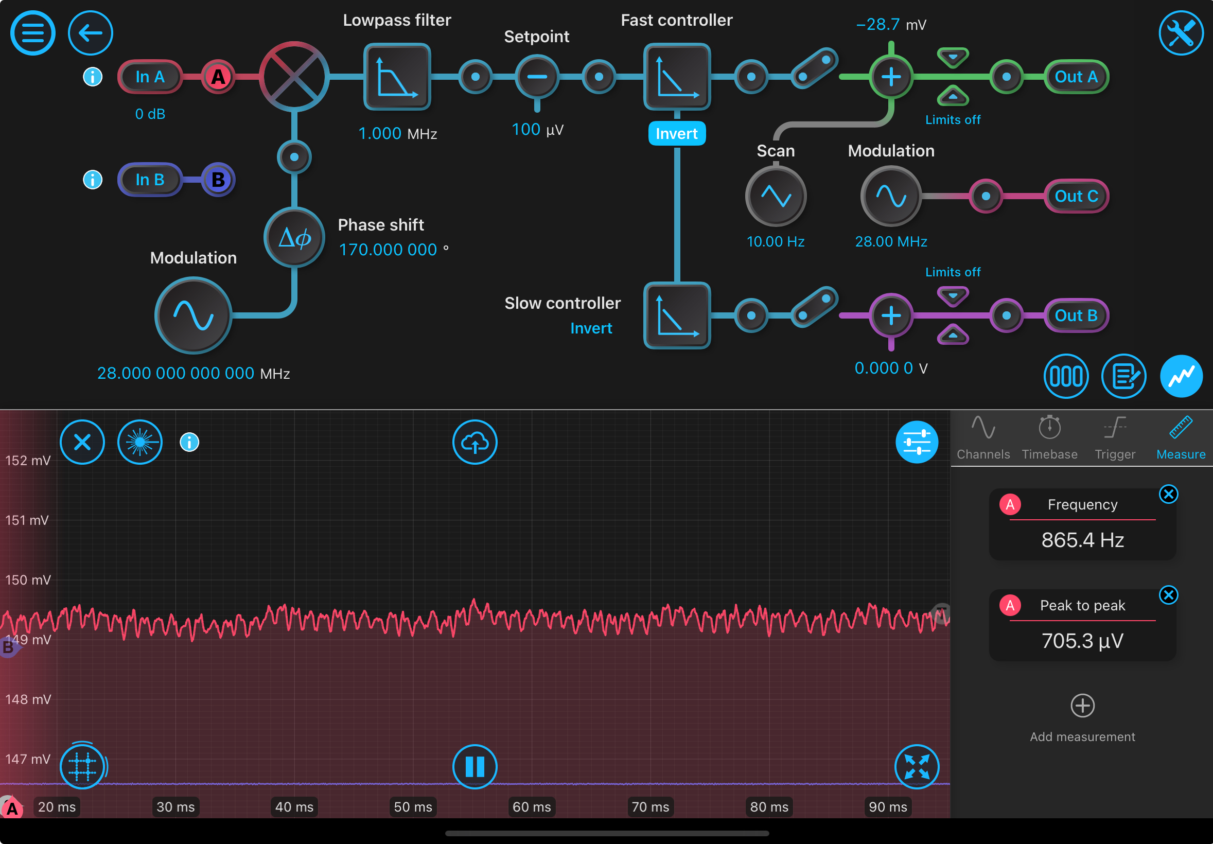
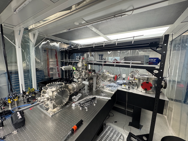
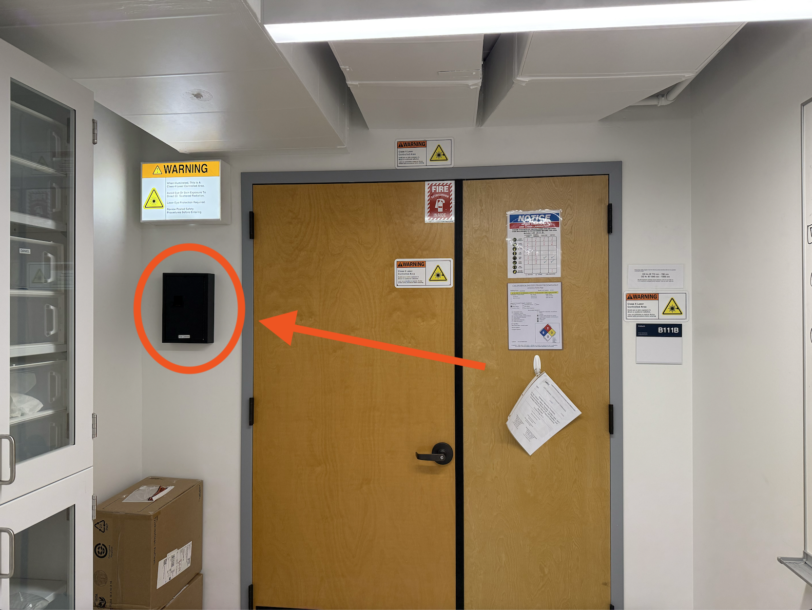
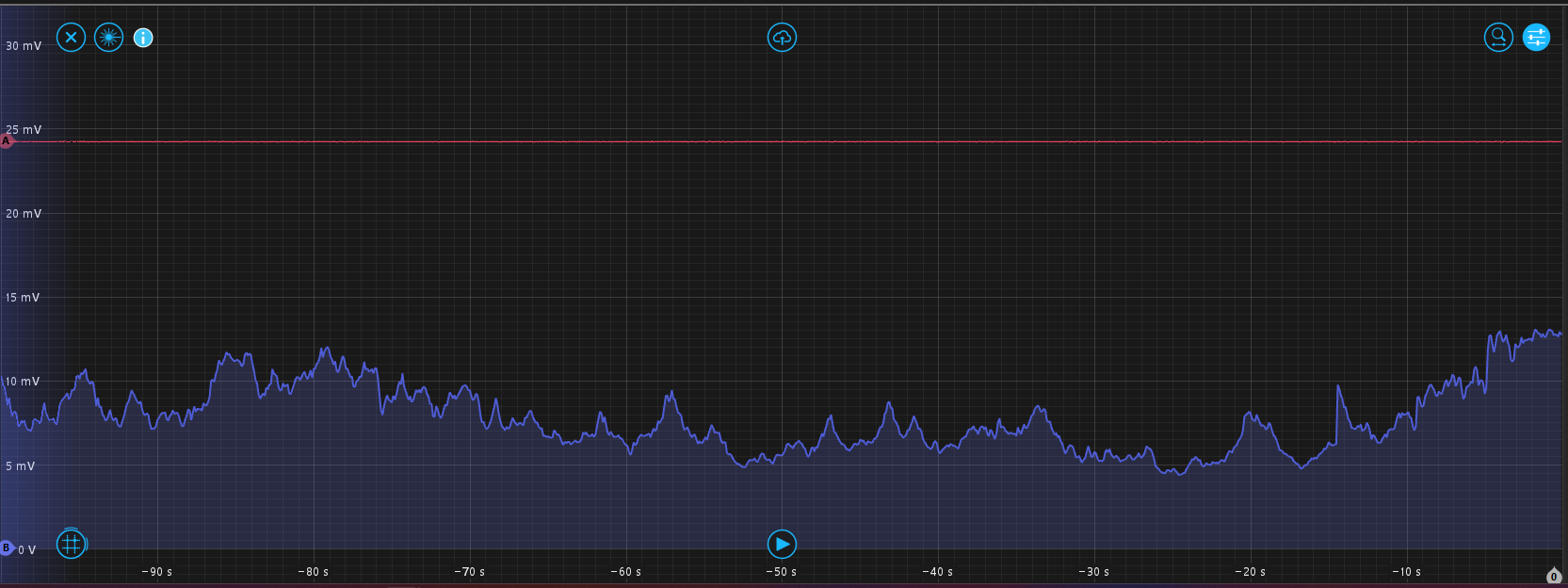
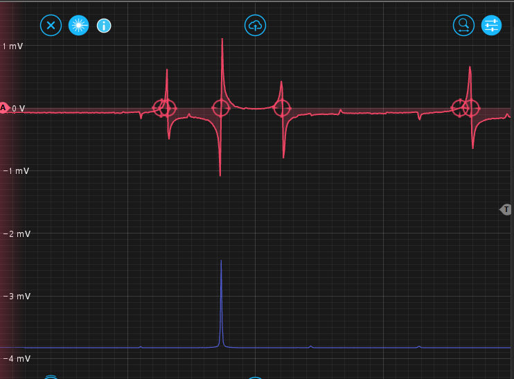
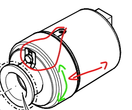
First, we added a mirror to direct the reflected 1550 beam to a Newport 1811 photodiode. This mirror is cramped against the imput mirror and is very close to clipping the input beam. We used a lens and an ND filter to focus onto the PD and prevent saturation. The REFL dip is not very low, suggesting the cavity is not critically coupled or we have alignment issues. Additionally, the old 900ish Hz oscillations are seen on this photodiode signal. Even though we are not using the Thorlabs laser, this is expected because the whole drawer is sharing ground with the Thorlabs laser. Hopefully this can be resolved by swaping out the Thorlabs power supply.

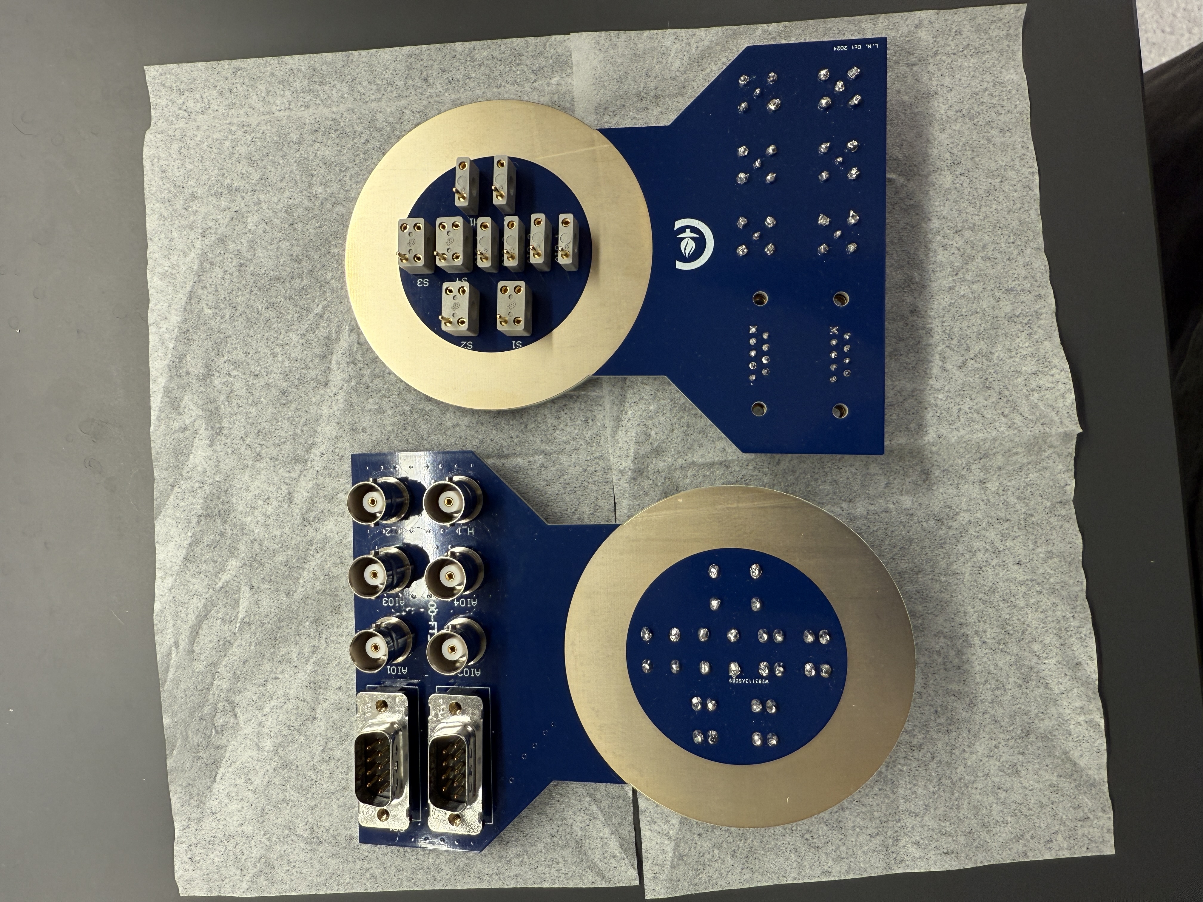
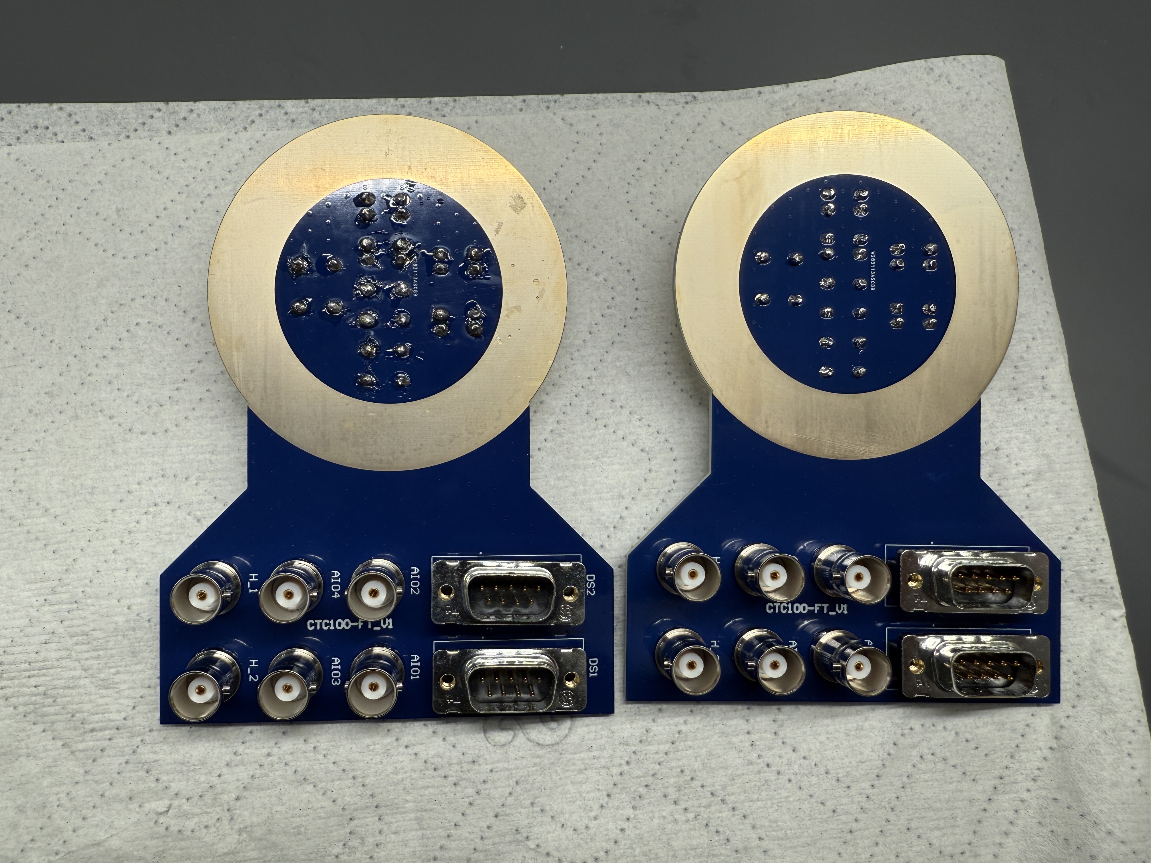
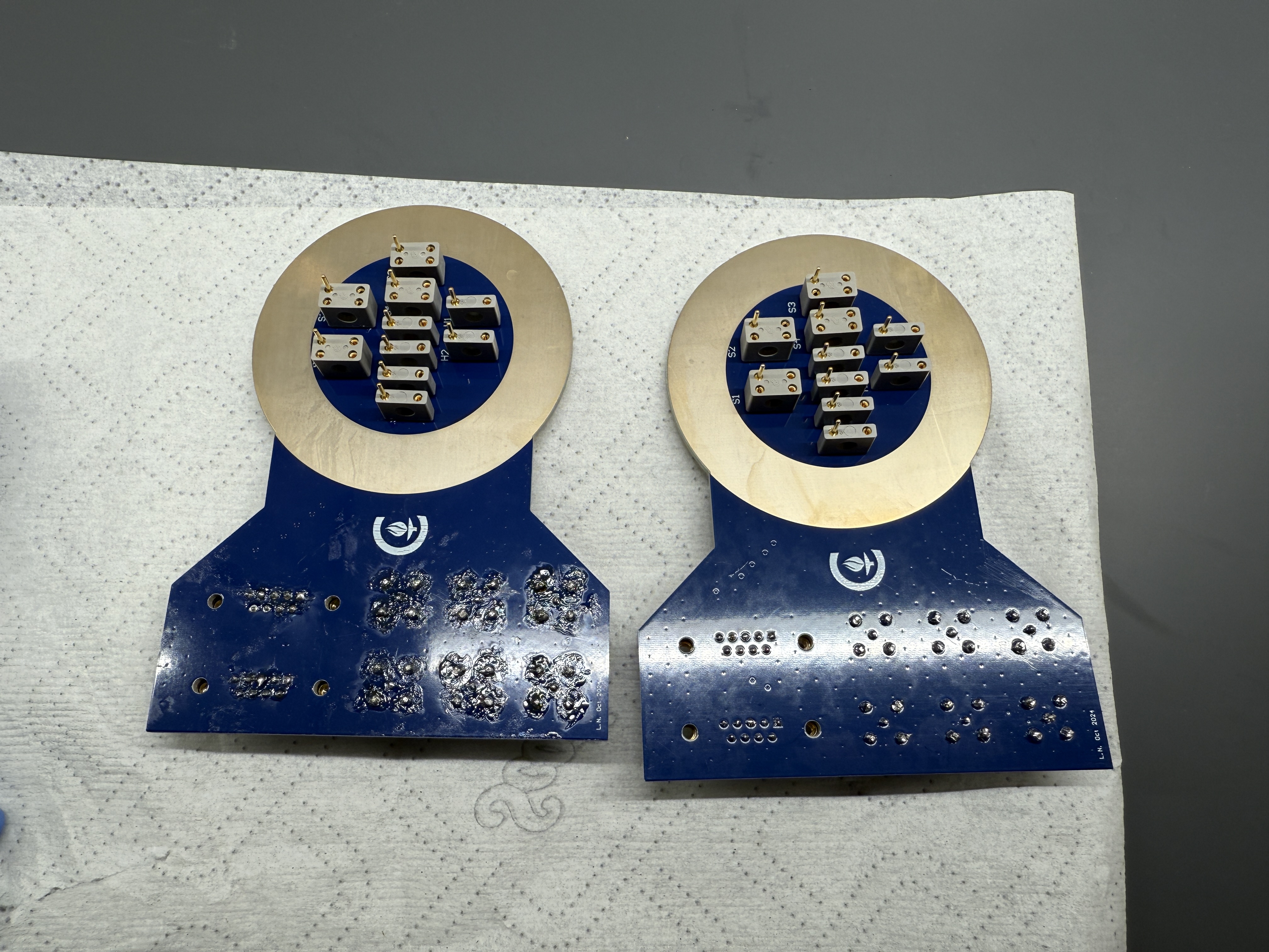
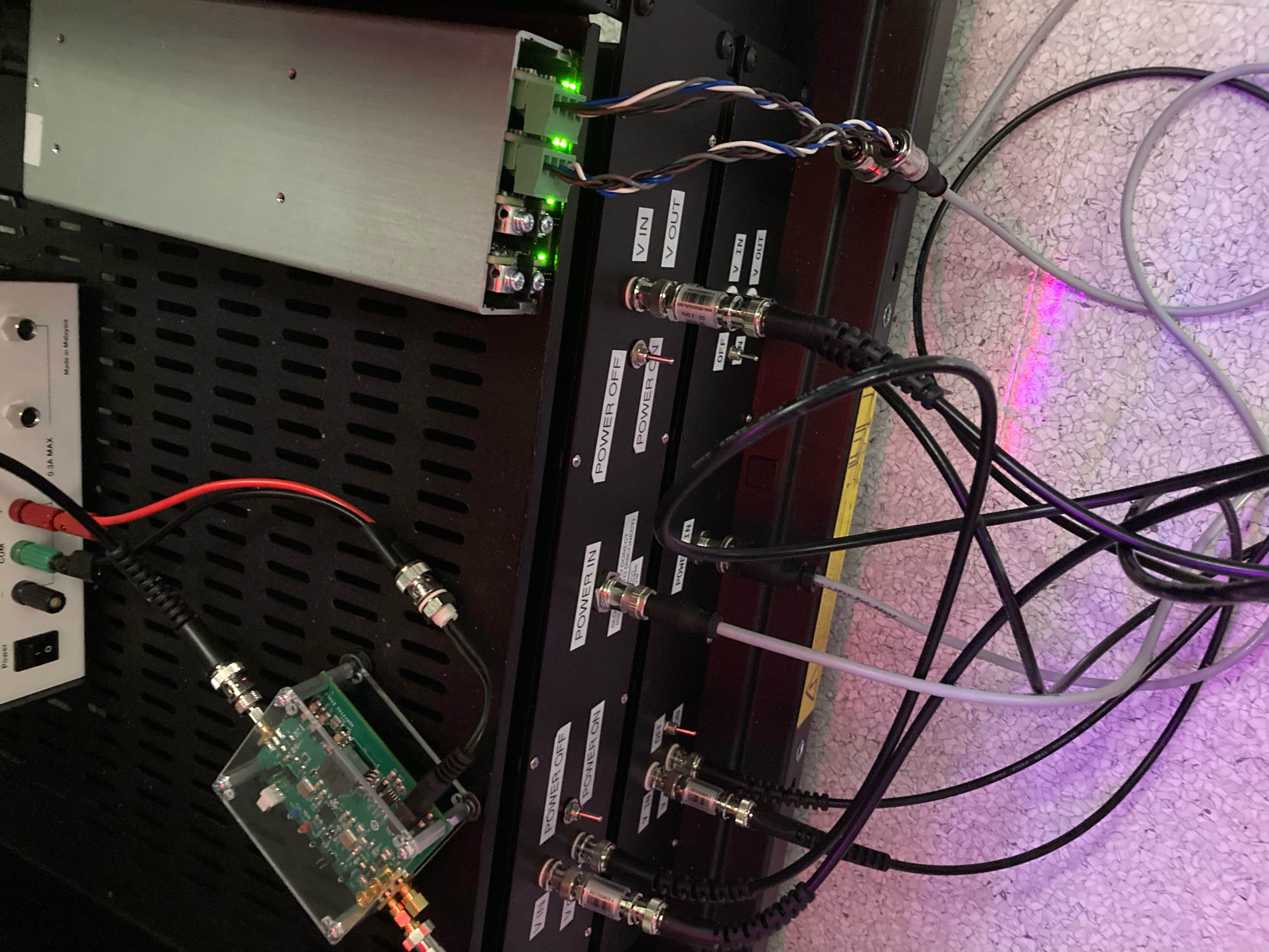
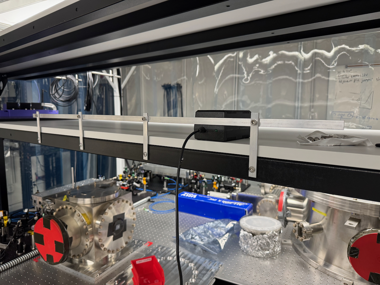
Next we installed a fiber EOM on the OFC 2 1550 test path. The RF drive required a SMP connector, which was borrowed from the LIGO lab from Todd Etzel. 

There was initially a large optical loss through the EOM, this was addressed by adding a half waveplate at the fiber input of the test path on the power distribution sled and rotating the polarization to maximize transmitted power.

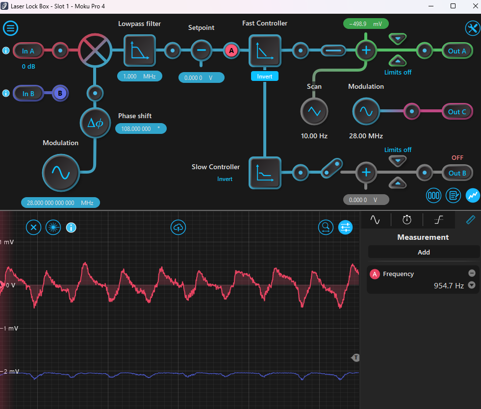
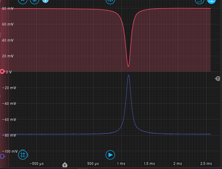
After tuning up alignment a bit, we achieved a lock of OFC 2 on 1550, actuating on the Teraxion laser.

We unplugged the Thorlabs laser so it is completely off, and this removed to 900Hz noise and improved the lock.

Electronics General
Jeffrey Wack - posted 16:20, Wednesday 02 April 2025 (12216)
AOM driver power supply consolidation

Both AOM driver chassis are now being powered by the same 'excelsys UX4' supply. It provides +24V and GND to the RF amplifiers as depicted in 12179.

After the change I checked that all 3 AOMs are still correctly deflecting a beam, and a twice shifted beam ends up at the fiber collimators.

Images attached to this report
Vacuum Systems General (GQuEST)
Daniel Grass - posted 12:18, Wednesday 02 April 2025 (12215)
Turbo and Ion Pump Controllers fully Connected Except to Wall Outlet

I connected the Agilent TwisTorr 74 Rack Controller to the TwisTorr 74 Turbo Pump, its cooling fan, and the FRG 702 pressure gauge. I also connected the ion pump controller to the ion pump. In case there is an accidental power on, I am waiting to plug them into a wall outlet until I am ready for them to be on.

Vacuum Systems General (GQuEST)
Daniel Grass - posted 12:17, Wednesday 02 April 2025 (12214)
2.75 in 1550 nm AR Coated Viewport installed on Laser Filter Cavity Input Vacuum Cube

I installed a 2.75" 1550 nm AR Coated Viewport on the Laser Filter Cavity (LFC) Output Vacuum Cube. I tightened the bolts to 10.7 Nm. 9.6 Nm was not enough to get a full steel to steel contact. I checked the other viewport I installed, and I could see a bit of a gap. I therefore tightened those bolts to 10.7 Nm as well and the gap reduced in size. Other than the hose from the turbo pump to the scroll pump, the LFC should be completely sealed and ready to be pumped out.

Images attached to this report
GQuEST Output Filter Cavities
Torrey Cullen - posted 12:03, Wednesday 02 April 2025 (12213)
Intercavity Mode Matching (OFC2 -> OFC3)

With the 775 OFC3 cavity lock successful, it is time to work on 1550. This requires mode matching the cavity. The light is diverging when it exits the cavity, with a waist of 581 um, roughly .6 m before the exit of the cavity (on M1 of OFC2). I adjusted the inter cavity mirrors position to maximize the amount of the length the light can travel as this is better for mode matching in this case. The two intercavity mirrors are at 15 and 18 inches from the cavity exit. The OFC3 cavity input mirror is at 29 inches. We want a waist here of 577.7 um (according to my finesse calculations of the cavity). JAMMT spits out an f=2m and f=1m lens solution based on the lens we have available. I've assembled these lens, moved the mirrors back into their positions, roughly placed them for now. See attached image for the calculation.

I am going to attempt to align into the next cavity using OFC2 1550 light. This poses a challenge because you need to make the two wavelengths coresonant and then lock on 775. Because the bandwidth of the 1550 cavity is so low and the lock quality is poor (and there seems to be 1550 -> 775 drift via the aom) it makes the test light being used very unstable. Will attempt this after lunch.

Images attached to this report
Vacuum Systems General
Daniel Grass - posted 22:08, Tuesday 01 April 2025 (12212)
5/16 in 12-point star Torque Adapter Wrench Sanded Down for Use on the Agilent TwisTorr 74 Turbo Pump

I used a belt sander to reduce the diamter around the 5/16" 12-point star Torque Adapter Wrench for Use on the Agilent TwisTorr 74 Turbo Pump since the turbo pump comes quite close to the screws, preventing the wrench from easily fitting around them.

The screw diamter is ~0.462-0.468". I ground down some of the wrench so that its radius was smaller than screw's. I confirmed the fit of the wrench around the screw that doesn't hit the pump.

Equipment Loans (GQuEST)
Daniel Grass - posted 22:01, Tuesday 01 April 2025 (12211)
Discussion on 4D Technology NanoCam HD Equipment Loan

I spoke with GariLynn Billingsley and Rodica Martin today about using the 4D Technology NanoCam HD to image the GQuEST End Mirrors with the surface correction mount. GariLynn understandably did not want the expensive profiler to be in Bridge instead of their custody, but said that we could continuously use it over the summer somewhere in Downs-Lauritsen with the exception of a few days when they need it. They think they can mount it on some optics table, although we hopefully will be looking for ~1 nm precision so the vibration isolation will be less important.

I am trying to figure out if there is a good way to mount the profiler so that it looks parallel to the ground instead of down.

Lab Infrastructure General
Ian MacMillan - posted 16:24, Tuesday 01 April 2025 (12210)
Key Box

I hung the box with the keys on the wall outside the GQuEST Lab under the light-up laser sign. See Key_box_location.png for location. The code for the box can be found in the lab secrets wiki. The information on the keys inside the box can be found on the key box wiki page. These are backup keys most of the things that have keys in this box are left unlocked. If you have a key for the box, add it to the paper in the box and to the key box wiki.

Images attached to this report
Lab Infrastructure General
Ian MacMillan - posted 15:35, Tuesday 01 April 2025 (12209)
Lista Cabinets Caster Platforms

[Ian, Alex, Torrey]

We assembled the platforms with casters on which the Lista cabinets will be placed. As seen in Lista_Wheels.jpeg, there are two fixed wheels and two swiveling wheels on each platform. The next step is to get facilities to lift up the Lista cabinets and place them on the platforms.

Images attached to this report
Vacuum Systems General (GQuEST)
Daniel Grass - posted 18:06, Monday 31 March 2025 (12208)
6 in to 2.75 in Reducer Flange and Ion Pump Added to Laser Filter Cavity

[Jeff, Daniel]

We added a 6" to 2.75" Zero Length Reducer Flange to a Laser Filter Cavity (LFC) 6" Gate Valve. I tightened the bolts to 34 Nm until the copper flange wasn't visible. I placed on the optics table a t-slot framing (80/20) structure with some viton to support the ion pump. We then placed the ion pump on the reducer flange and I tightened the bolts until the copper flange wasn't visible. 

The cable to the ion pump fits, but it might constrain the composite 2.75" CF Angle Valve (that would go to the leak checker) from opening fully.

GQuEST Output Filter Cavities
Torrey Cullen - posted 15:53, Monday 31 March 2025 (12205)
OFC3 Next steps

I would like to start on the 1550 path of OFC3. There are two ways to do this. We could just set up a test path directly from a fiber. With the intracavity alignment already done this seems like it is not worth the time. This just leaves aligning the light coming out of OFC2. The problem with this is as follows:
You can't PDH on 1550 in OFC2 as this was never set up. This means we have to lock on 775 and adjust the aom frequency so they are coresonant. This is bad for two reason: 1) the lock quality is very poor and 2) the two wavelengths are drifting relative to each other. You can fix this by adjusting the frequency of shift on the 775 path so that they are realigned, but continously doing so would be a pain. If you lock them while coresonant, and just watch the 1550 output over time it fluctuates wildly on a seconds time scale. I interpret this as the 1550 light drifting where it is along the lorentzian output peak. It does not seem feasible to try and align a cavity with this as your input light.

An alternate plan could be we fiber couple every cavity together. Use constant light from a real source to align and then just plug in your filter cavity output light fiber once its aligned. This introduced more loss into the GQuEST readout though. If anyone has ideas on this it would be appreciated.

Images attached to this report
GQuEST Output Filter Cavities
Torrey Cullen - posted 13:41, Monday 31 March 2025 (12204)
OFC3 Initial 775 Lock

Continuation of 12198.

I removed the lens in transmission of the cavity. This allowed me to see it was cleary clipping something circular. I walked the input beam and intracavity mirrors until the clipping was no longer observed. With this clipping gone was able to tune the alignment by eye on the camera a little more. At this point it is much better to use PDs to fine tune the alignment. I installed a 50:50 beam splitter in transmission as well as a PD. Additionally, I installed 2 mirrors in reflection of the cavity that act as steering mirrors onto a REFL PD. Next I aligned onto the REFL PD to allow for locking. While the cavity is locked, you can see the TRANS beam on the card to allow for easier alignment onto the TRANS PD.

775 path is fully installed and aligned. A cavity scan shows the cavity is well aligned. While locked, it seems there is some periodic signal on the error signal (this is laser locked with the teraxion) that is causing some drops in the amount of transmitted light power. By changing the coupling on REFL to DC you can check the visibility on the REFL PD. It seems pretty good, but may be improved by a lens as the diode is very small on these fast PDs used for PDH.

Images attached to this report
Vacuum Systems General (GQuEST)
Daniel Grass - posted 18:42, Friday 28 March 2025 (12203)
Agilent IDP 7 Placed on Platform and other Vacuum Parts Unboxed for Laser Filter Cavity

[Jeff, Daniel]

We unboxed the Agilent IDP 7 scroll pump and placed it on a platform meant to hold it. We placed this in the B111B Mobile Clean rooms close to its final location. We will need a 4 ft long KF25 hose (MH-QF-B48 on Kurt J Lesker is the cheapest option; we don't need additional features) to extend the included hose from the TwisTorr 74 turbo pump to the IDP 7. We have a 4 ft long 2.75" CF hose that's meant to be used in case we need to move the turbo off the LFC for vibration purposes (shouldn't be an issue if we use the ion pump to maintain vacuum), but the cost of two converters is about the same so we should get a single hose.

We also unboxed a lot of the other small components like fans, power cords, and the turbo controller. I forgot to install the inlet screen for the turbo pump, so I should take off the turbo, add it, and put the turbo back.

Lasers General (GQuEST)
Daniel Grass - posted 18:21, Friday 28 March 2025 (12202)
GQuEST Seeder Laser Fiber Components for Old Layout Put Away

[Jeff, Daniel]

We put away the 75:25 fiber beam splitter, the FPC562 - Fiber Polarization Controller, some small items, and the breadboard that was on the B111B mobile clean room shelf. The 75:25 fiber beam splitter is in the bottom of the lista cabinet by the mobile clean rooms and the FPC562 is in the white drawers on the south wall (in a labeled drawer). We moved the now-empty breadboard into B102 by the other breadboards.

Vacuum Systems General (GQuEST)
Daniel Grass - posted 01:42, Thursday 20 March 2025 - last comment - 17:41, Monday 31 March 2025(12187)
6 in 6 way cross for the Laser Filter Cavity initial assembly

[Jeff, Daniel]

We assembled a 6" to 2.75" zero length reducer flange on a non-rotatable flange of the 6" 6 way cross for the Laser Filter Cavity (LFC). The 6 way cross has 3 rotatable flanges and 3 non-rotatable flanges. Opposite sides have one of each.

After tightening the bolts to 34 Nm and seeing no copper gasket, we added the Agilent FRG702 Pressure Gauge. The magnet was 0.6" below the main body of the gauge before moving it up to fit the screws. We added the screws and tightened as hard as I could with the ~8" long wrench. The copper gasket wasn't visible. We tried to move the magnet down to its original location but could only get it 0.45" in down and unsecured.

We tried to add the 6 way cross to the 8" to 6" reducer tee but it was too heavy for 2 people if one person help up the rotatable flange on the tee. We'll need a 3rd person for this job.

Comments related to this report
Daniel Grass - 17:41, Monday 31 March 2025 (12207)

I aligned the magnet's rotation as shown in the attached picture from my Agilent contact. I also moved the magnet away from the body of the pressure gauge, but apparently this degree of freedom doesn't matter as much. I did find a pressure gauge that works down to 10^-4 Torr from the Holometer. Maybe we can attach that and use it as a check.

Images attached to this comment
SNSPD General (GQuEST)
Daniel Grass - posted 17:12, Thursday 13 February 2025 - last comment - 15:04, Saturday 05 April 2025(12137)
Aluminum KF50 Centering Rings Machined to hold PCB in SNSPD Dewer

[Alex, Daniel]

I got two aluminum KF50 Centering Rings from Nick Hutzler's group and machined them in the lathe to remove one of their lips so that they can hold a PCB that interfaces with the inside and outside of the Dewer. I clamped them on the outside lip with a 6 jaw chuck. I used a moderate amount of clamping force (~90 degrees of rotation with the chuck key) to hold them. I slowly increased the spindle speed to ensure the rings wouldn't fly off; I used a final spindle speed of 1700 rpm, which is pretty standard for aluminum and a carbide tool. I kept the x-axis of the lathe at around 1.93" and slowly moved the tool in the z-axis to remove the lip. I needed to take off 0.080" of material. For the last few thousands of an inch, I moved the tool in the x-axis instead of the z-axis. I then used a deburring tool by hand to remove any burrs from machining. I could not see any markings from the clamping jaws.

Tomorrow, I will clean and start to bake out these centering rings.

Comments related to this report
Daniel Grass - 12:32, Friday 14 February 2025 (12138)

We cleaned the centering rings with the normal aluminum procedure of successive 3 minute baths and scrubs of 1:30 Simple Green:DI water, DI water, and isopropanol. We put it in the vacuum oven to bake out at 120° for 48 hours since we don't know the alloy of aluminum. 

Daniel Grass - 21:39, Tuesday 18 February 2025 (12141)

I turned off the vacuum pump and closed the valve to the vacuum pump around noon today. According to the vacuum oven, the bakeout lasted 49-50 hours. We can store these parts under vacuum unitl we need them or the vacuum oven.

Daniel Grass - 17:32, Tuesday 04 March 2025 (12161)

I machined 3 more aluminum KF50 centering rings exactly like I did the first 2.

Daniel Grass - 18:19, Wednesday 02 April 2025 (12219)

We moved the two cleaned centering rings out of the oven and put them in UHV foil and an antistatic bag. We repeated the cleaning process for the three dirty rings and are baking them out.

Daniel Grass - 15:04, Saturday 05 April 2025 (12226)

I turned off the vacuum pump and closed the valve to the vacuum pump

Lab Infrastructure General (GQuEST)
Daniel Grass - posted 19:18, Monday 11 November 2024 - last comment - 18:17, Wednesday 02 April 2025(11976)
Guardrails made and installed onto shelf above optics tables

[Ian, Sander, Daniel]

I designed some guardrails that go 3" above the M6 tapped holes of the shelf above the optics tables in B111B. I used 1/8" thick, 1/2" wide aluminum bar. There were 3 piece types (all holes centered along the 1/2" width):

Vertical bar: 4" long; 0.24" (C drill) diameter hole 0.5" from bottom; 0.27" (H drill) diameter hole 3.5" from bottom

Long horizontal bar: 36" long; 0.27" diameter holes at 0.78", 1.5", and 3 more holes with a regular 250 mm spacing beyond 1.5" to match the shelf hole pattern.

Short horizontal connection bar: 19" long; 0.27" diameter holes 0.375" from side and 2 more holes with 9.125" spacing

This short horizontal connection bar is designed to be replaced by a patch panel if desired.

Ian helped me drill some holes and Sander helped me install the connection bars.

We were not able to install 1 long and 1 short horizontal bar because the seeder breadboard overhangs the shelf by ~1". 


See attached photos.

Images attached to this report
Comments related to this report
Daniel Grass - 18:17, Wednesday 02 April 2025 (12218)

[Jeff, Daniel]
 

I drilled a few more parts and installed the last pieces of the guardrail since we moved the breadboard.

Displaying reports 101-120 of 1093.Go to page Start 2 3 4 5 6 7 8 9 10 End