[Jeff, Daniel]
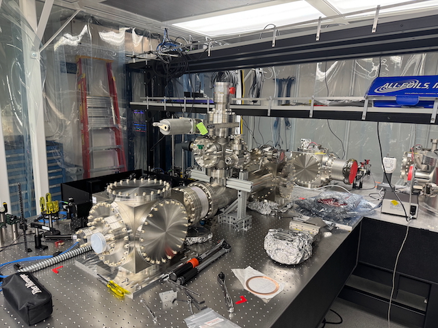
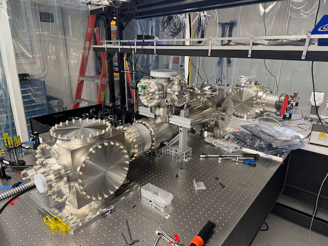
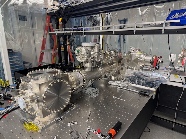
We unboxed the Agilent IDP 7 scroll pump and placed it on a platform meant to hold it. We placed this in the B111B Mobile Clean rooms close to its final location. We will need a 4 ft long KF25 hose (MH-QF-B48 on Kurt J Lesker is the cheapest option; we don't need additional features) to extend the included hose from the TwisTorr 74 turbo pump to the IDP 7. We have a 4 ft long 2.75" CF hose that's meant to be used in case we need to move the turbo off the LFC for vibration purposes (shouldn't be an issue if we use the ion pump to maintain vacuum), but the cost of two converters is about the same so we should get a single hose.
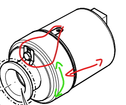
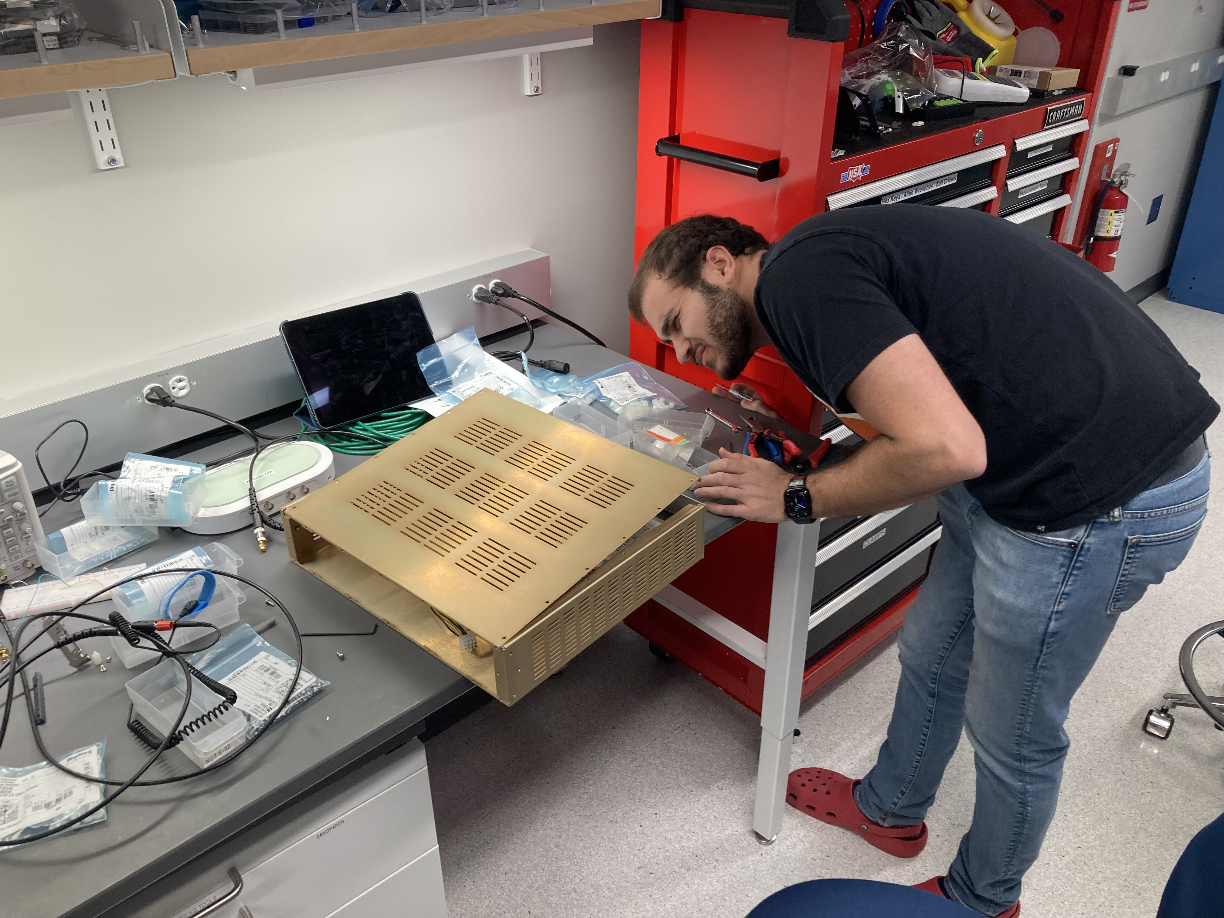
We also unboxed a lot of the other small components like fans, power cords, and the turbo controller. I forgot to install the inlet screen for the turbo pump, so I should take off the turbo, add it, and put the turbo back.