[Sander, Rodica Martin, Daniel]
Summary
We imaged the surfaces of our crystalline silicon optical substrates from Knight Optical using an optical profiler from 4D technology. The substrates are dusty, which significantly increases the surface RMS roughness. Removing the dust, either by cleaning with First Contact or by digitally masking the surface image to exlude dust, improves the RMS significantly. From these observations we conclude RMS roughness of all substrates is certainly < 0.3 nm and likely < 0.2 nm. Given these numbers and estimated scatter losses due to this roughness (see post 12119), we believe no further polishing is neccesary.
Measurement procedure
We unpackaged the substrates, handling them either by suspending them on some lens tissue and holding the lens tissue, or by holding the barrel with gloved fingers. We then aligned the optic visually with the center of the imaging aperture of the profiler. We then focussed the image using the profiler's software and manual focussing controls. The images captured were 3.547 mm by 4.255 mm, or 2056 px by 2464 px. An average of 32 images was taken. We saved .4D data files for all measurements. We marked the packaging of each subtrate that we measured with a serial number. According to Rodica the profiler software has some functionality to remove artefacts such as those from dust and fringes, but this removal is incomplete as these artefacts still show up in the image and contribute to the RMS.
Results
Spoked Circular and Octagonal (SC-2in/SO-2in)
The spoked optics are the cleanest substrates out of all measured. We managed to image unmasked sections of some of these without any dust present, giving RMS < 0.18 nm. These images still have fringe artefacts so this is to be taken as an upper bound on the RMS.
Unspoked Circular and Octagonal (UC-1in/UO-1in)
The uspoked optics are very dusty. We cleaned one side of an UO-1in substrate with First Contact (peeling off 35 min after application, Rodica says this reduces residue left after peeling off compared to waiting longer) and compared to the other uncleaned side of the optic. This uncleaned side has RMS = 0.675 nm, the cleaned side had RMS = 0.194 nm. Applying a digital mask, excluding parts of the image with dust, reduced the RMS of the dirty side to 0.165 nm.
Unspoked Wedged Circular (UCW-1.5in)
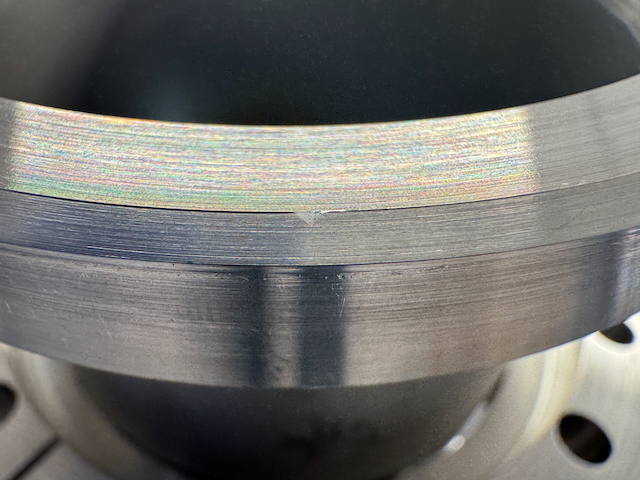
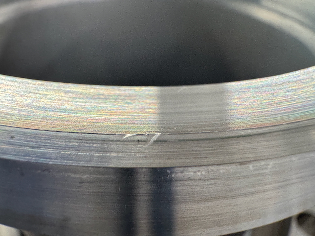
These substrates are quite dusty (like the other unspoked optics, they were all part of the same order, so this makes sense). Notable arc-shaped scratches were seen on both sides of the optics, presumably from the procedure that produces the wedge. The wedge was observable by focussing the profiler on one side and observing the changed fringe pattern once the substrate was flipped over. Images of a substrate with lots of scratches and some dust and fringe artefacts had RMS = 0.298 nm and RMS = 0.274 nm. Given the RMS improvement from cleaning dust and masking seen from other substrates, I would estimate the RMS is actually < 0.2 nm.
Data for all measurement is in the attached spreadsheet (will upload to the wiki, we might want to add more data into it), as well as some screenshots of the measurements.