[Briana, Ian]
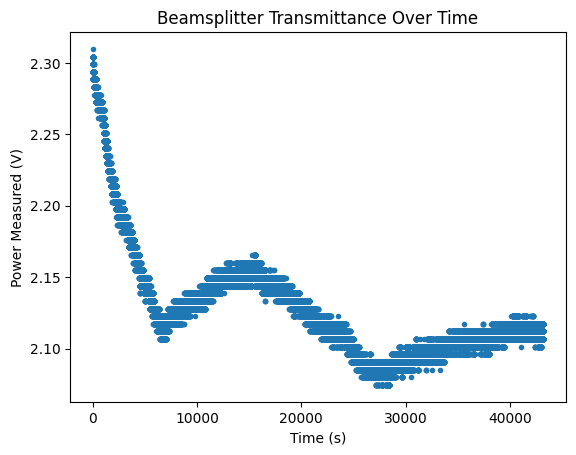
Unfortunately, the polarization drift test run last night does seem to be significant (see polarizationdrift). This was done at an operating current of 101.2 mA, temperature of 9.924 kOhms. I am running another test to see if the drift is as obvious at a higher temperature/current.
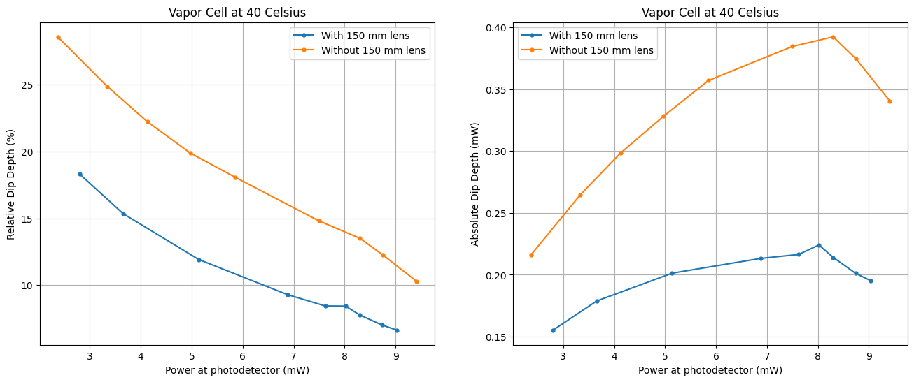
Before I mess with the laser and consequently the alignment/beam profile, I took dip depth measurements with the 150 mm lens. I maintained the same current (145 mA) for all values, which is why the dips in comparison.pdf (legend shows the power reaching the photodetector in mW) correspond to approximately the same wavelength (and also temperature, although this is not plotted). By turning the waveplate, the power reaching the vapor cell and photodetector is changed from ~3mW to 12 mW. Even though there is polarization drift, the fluctuations in power are not so significant that it should drastically affect the power by multiple mW, which is what I generally changed the power by. When I plot the dip depth, the results hold: a large beam size produces a larger absorption dip depth: dipdepthcomparison.png. Data regarding the beam profile difference is found here: 7_25.xlsx. The lensed beam is smaller by about 200 microns initially and ~1000 microns by the vapor cell exit. This is so far the best experimental result (with the most consistent conditions) and should be referred to for dip depth. Saturation clearly occurs- will add some context about this soon.
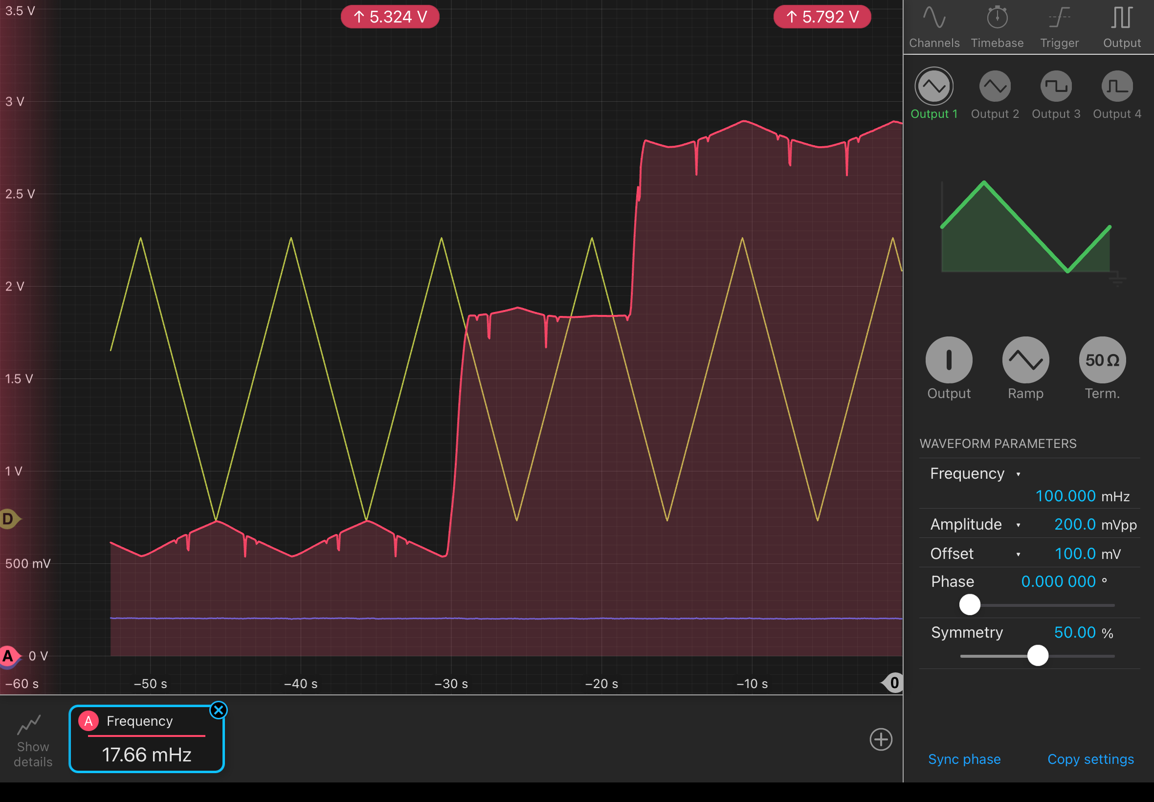
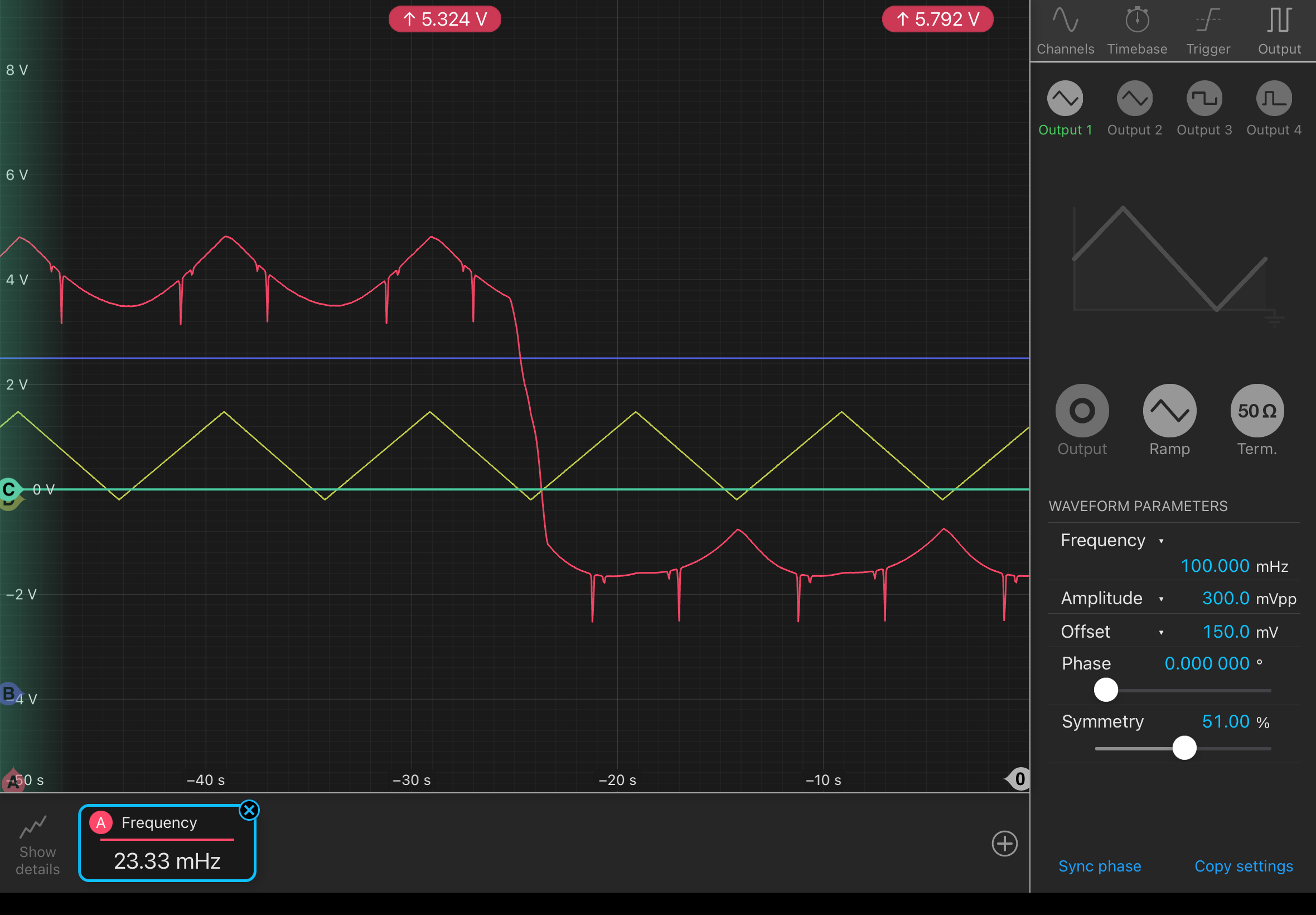
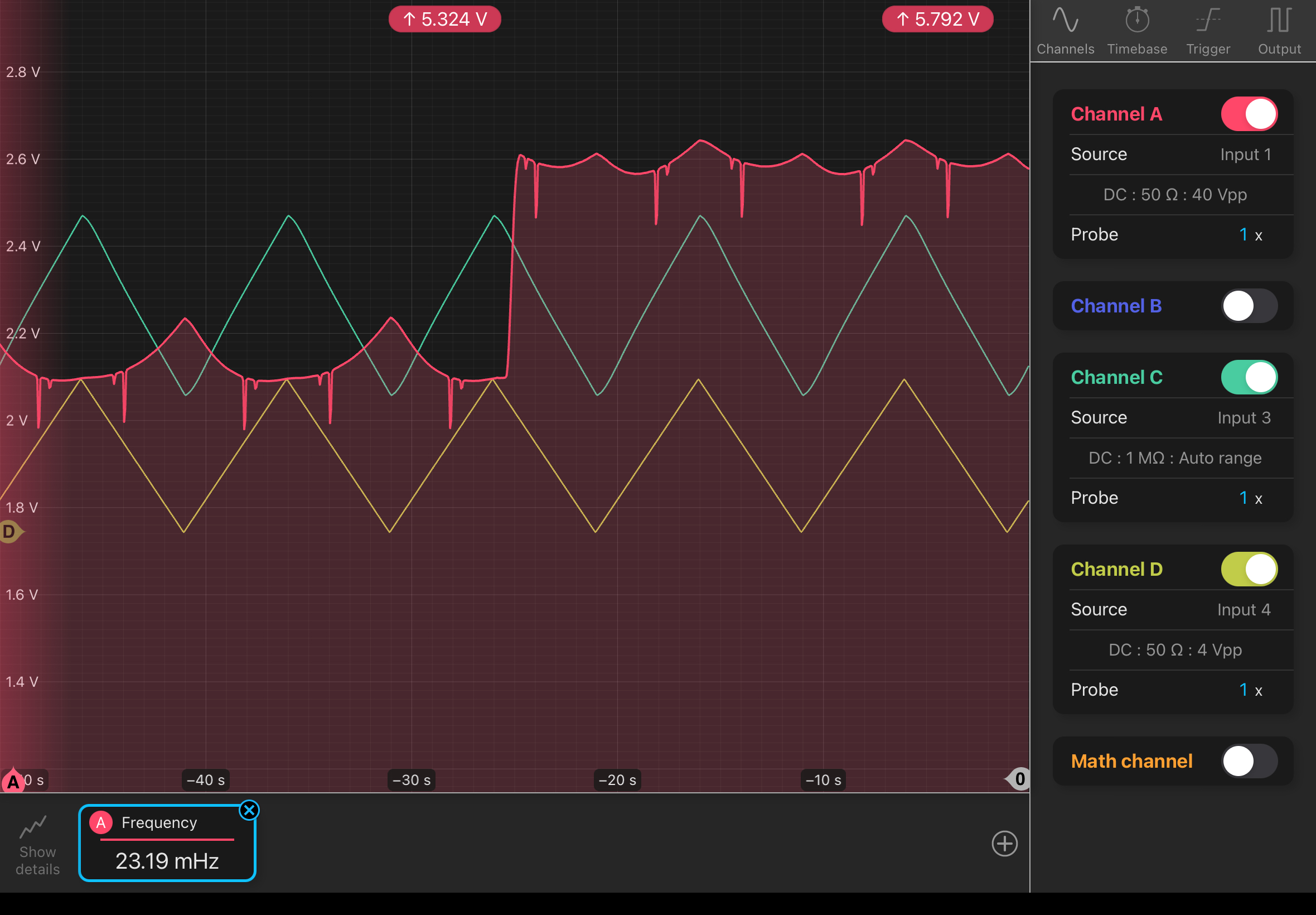
While doing this experiment, I ran into another issue with the polarization drift. As you increase the temperature (resistance decreases), you should get less power based on 780 laser specs. However, you see an increase in power at a certain temperature. This causes strange behaviors as shown here: pic1, pic2, pic3, where the yellow/green show the inverse of scanning temperature. The red line should generally follow the trend of the yellow line, but in fact does not at certain powers. We found that if you place the powermeter in front of the beamsplitter, the temperature power relationship is fine. However, after the beamsplitter you begin to see this weird behavior. This is probably again because the increasing temperature affects the polarization of light coming out of the polarization maintaining fiber. The issue has to be that the input light to the laser fiber is not oriented along either the slow/fast axis, which means the light coming out has an elliptical polarization that is heavily dependent on mechanical/temperature perturbations. It does not seem like you can change the input light based on how the butterfly laser came. Maybe you can rotate the fiber ouput in some way with the fiber collimator to solve this issue? Another way would be to couple this output to a polarization maintaining fiber, although not sure how feasible this is given resources/space.
Also, the issue with the CTRL OUT channel displaying fuzz was because I can't read and enabled the wrong channel. Still not sure what exactly accentuates the smaller dips in the main absorption dip- they were very very faint in these measurements.