[Briana, Ian]
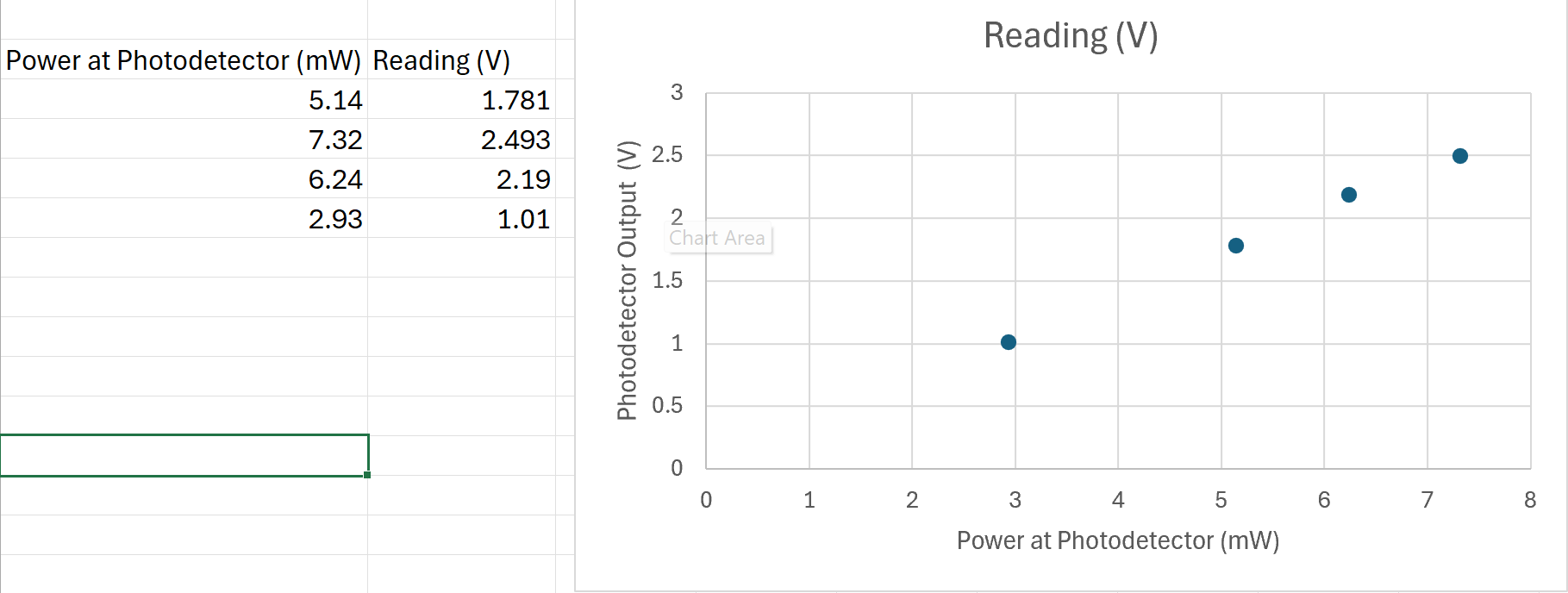
The varying levels at which the photodetector saturated was a concern. For example, in the 7/25 data, the photodetector was saturating around 3.3 V. Earlier today, 9.4 mW at the photodetector (current controller at 145 mA) saturated the detector, which was a setting that we were able to achieve without issue on 7/25. The photodetector response could even reach 7V in some previous data. I measured the power incident on the photodetector and the outut reading to confirm that the photodetector reading is linear as expected from specs, which it seems to be (linearphotodetectorresponse.png). The solution for this issue was to set the Vpp on the channel of the photodetector to 40 Vpp so that it could reach a higher voltage- it was cutting off at 2.5 V because the setting was only at 4 Vpp.
This still does not explain a few things to me. First, the photodetector reading should only read 0-5 Volts for a 50 Ohm impedance, which is what the BNC cable provides. In our measurements today, we could achieve >5V without saturation. There were no setting that I am aware of that were set to add gain/amplification. Also, the PDA output has a 50 Ohm series resistor and this alongside the output impedance produces a scale factor that is proportional and determines the output (in Volts) from the photodetector. The scale factor is R_load / (R_load + R_series) so if the Moku is providing a 50 Ohm impedance versus a 1 MOhm impedance, the output voltage should be different by a scale factor of around 2. This is not the case also when we change the Moku settings from 50 Ohms to 1 MOhm. However, with this 40 Vpp setting, we get bigger dips (around 0.7 V at max) than before because obviously the signal is not getting limited by the 4 Vpp setting, so maybe it is fine?? Not sure what I'm missing with how the photodiode works.
Either way, if only a flat line is seen from the photodetector, it is probably saturating. This is also probably the case for why the multi-instrument mode (MIM) oscilliscope was different from single instrument oscilloscope- MIM seemingly only allows 400 mVpp and any attempt to set it to 4 Vpp is accompanied by automatic attenuation. Not sure how to fix this setting yet.
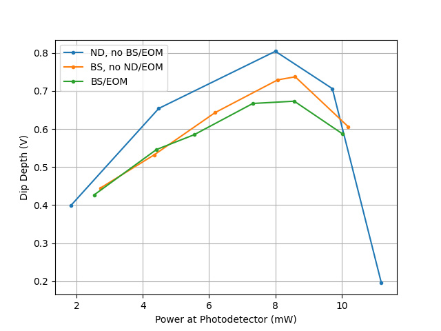
I took dip depth measurements again today to start repeatability confirmations, which I will test tomorrow. I first removed all the beamsplitter/EOM stuff and took a dip depth measurement using ND filters to vary power. Then, I put the beamsplitter in and measured. Finally, I aligned with the beamsplitter and EOM. The measurements of dip depth are compared here: dips.png. The dip depth measurements (done roughly using the voltage lines on the oscilloscope) seem to agree with the saturation point from previous data (7/25). It seems that as the light passes through the beamsplitter/EOM, there is a decrease in dip depth. This does not have to do with losses since the x-axis of these plots is the amount of light hitting the photodetector. This could be, as Ian suggested, because the vapor cell somehow responds differently to a certain polarization of light (currently p-polarized light passes through the vapor cell). I can try these dip measurements again with s-polarized light instead to see if it responds differently. Note: the very last data point of the graphs with the beamsplitter and beamsplitter/EOM (highest power) was taken at a current of 154 mA to get to the necessary power (because of losses through the EOM/beamsplitter). The maximum power that the beamsplitter could achieve was the power at the second to last data point. It would be good to take data also at a higher operating current, which could also answer the question if the dip depth saturates at the same power for different currents. Because the polarization still drifts, some of the temperature scans are weirdly inverted. Not shown error bars: uncertainty in power at photodetector is estimated to be around 0.05 mW, uncertainty in dip depth around 0.05 V. See data here: 7_26.xlsx.
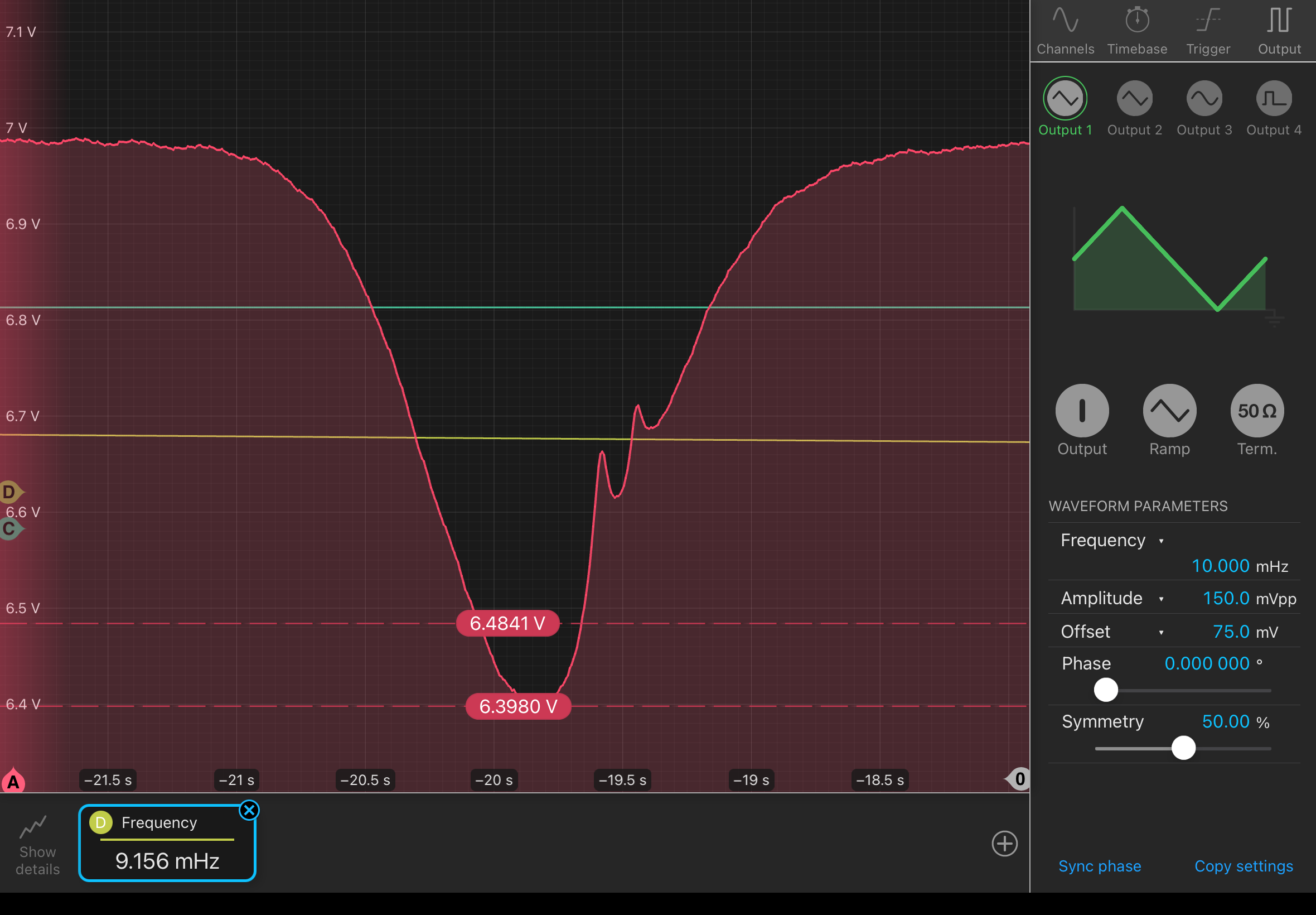
Also, you can see the small dips! Again, not sure what enables the resolution to capture these (alignment? right orientation/power through the vapor cell?) but it's nice to see them: c142_p6_main_20240729_181728_Screenshot.png. Will fit line profiles to them to see what the differences in wavelength are (corresponding to what transitions).
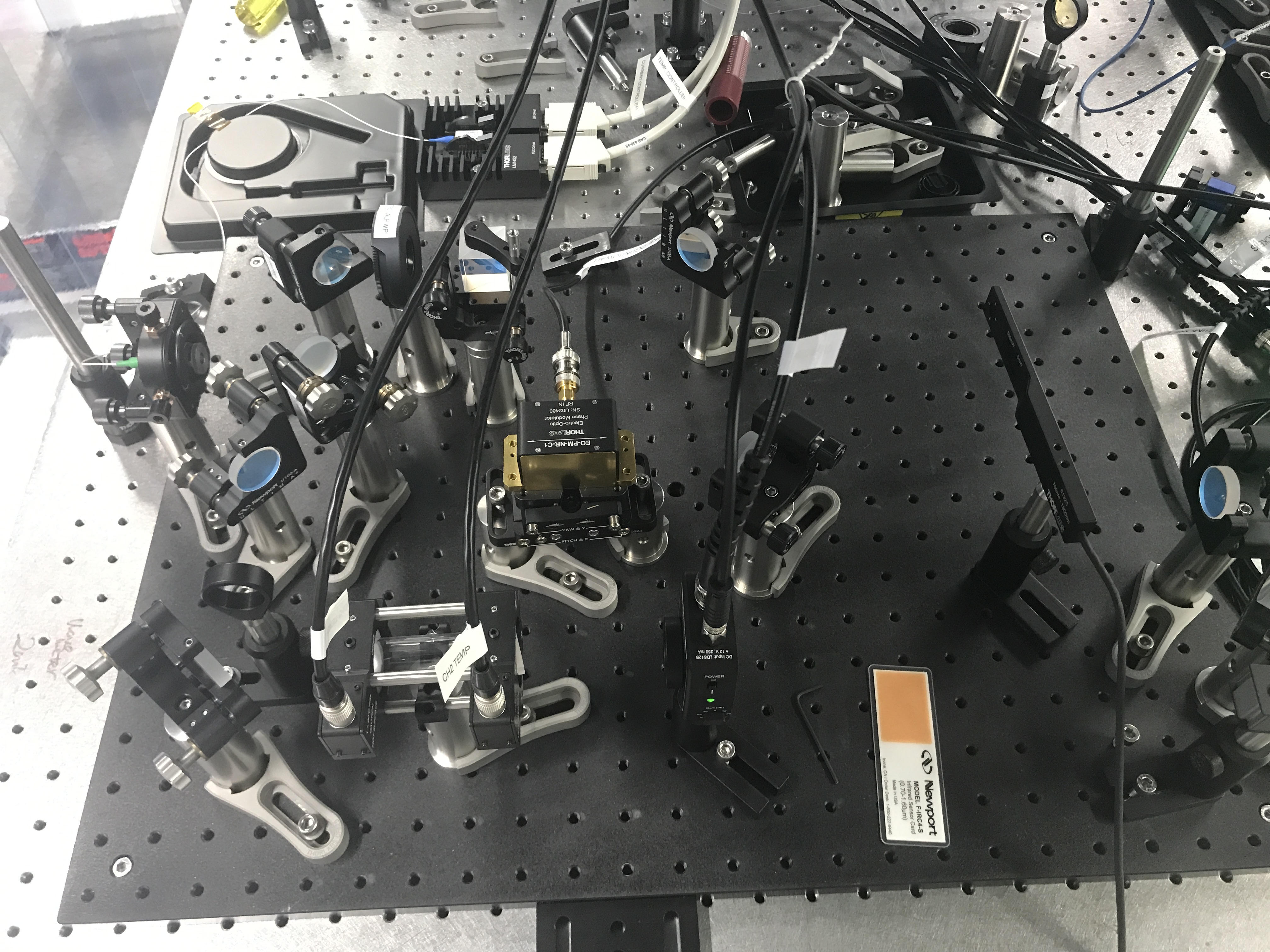
There may be additional losses from the EOM if the output from the laser changes in polarization (drift) since the efficiency through the EOM is determined by the polarization. We are going to try turning the laser tomorrow. Current setup: IMG_2374.jpg.
Labelled inputs/outputs to Moku as follows:
Input 1: Photodetector measurement (labelled Caitlin Clark).
Input 2: input to EOM, coming from Output 3 (labelled Simone Biles).
Input 3: CTL OUT (labelled Paige Bueckers).
Input 4: TUNE IN (labelled Joey Votto), coming from Output 1.
Output 1: temperature control (labelled Joey Votto).
Output 3: input to EOM (labelled Arike Ogunbowale). Output 2/4: none