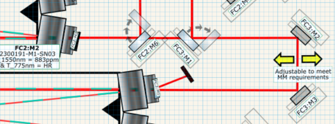
I've updated the layout diagram for OFCs 1, 2, and 3 for its current configuration in B111B. I've laid out all the optical elements on the table for a proof of concept. It will be cramped but it should fit. This configuration should allow continuous building and testing of OFC3 while allowing for chained cavities in the future. Couple of other notes:
-For this to be fully functional we need to buy a 775 50:50 BS and a thorlabs PDA10A2.
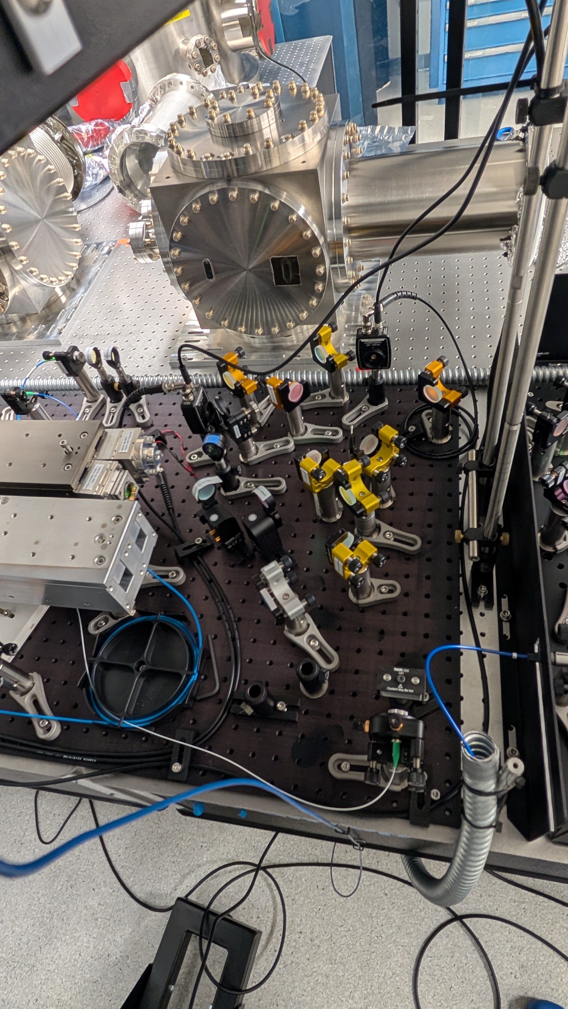
-Note the oxidation (I think?) in PXL_20250124_000346938MP.jpg. Unsure if we care, just pointing it out.
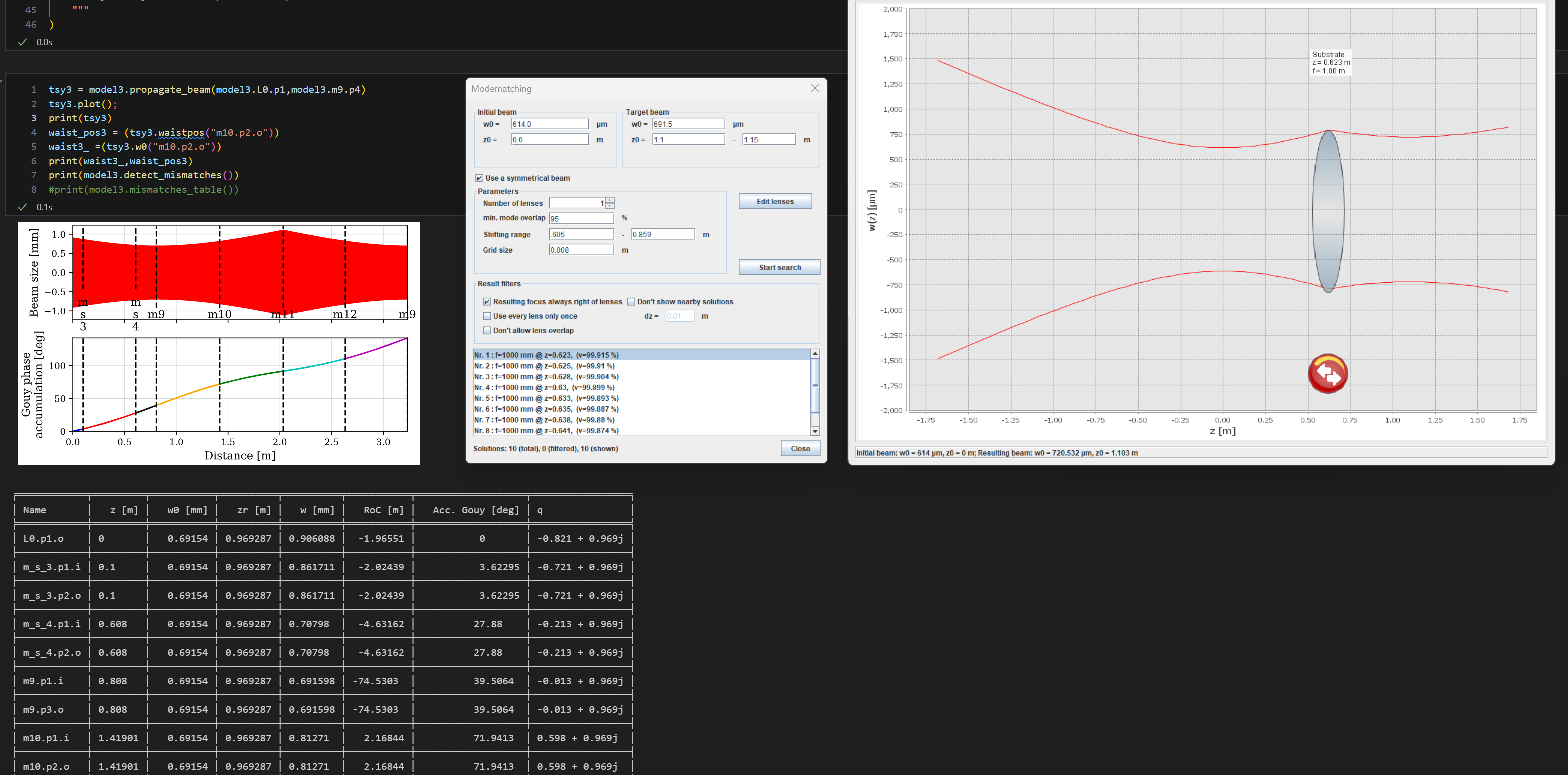
-Still need to calculate mode matching solutions for both 1550 inputs and the 775 inputs.
-The .svg that created this image is at "\Nextcloud\GQuEST\Layout_Mockups\readout_FCs_1_2_and_3.svg"
-It is unclear how the output of OFC3 will get to the eventual OFC4.

My current plan is to add two additional 1/8 inch spacers to OFC3. This should change the FSR by c/2.4 - (c/(2.4+2/8*.0254)) ~ 300kHz. With a linewidth in the 10's of kHz this should provide enough separation between cavities. This means the waist of the 1550 beam should be 691 um which can be achieved by putting a f=1m lens just after the output of OFC2 (99.92% mode overlap).