Daniel Grass - posted 12:31, Wednesday 29 January 2025 (12101)
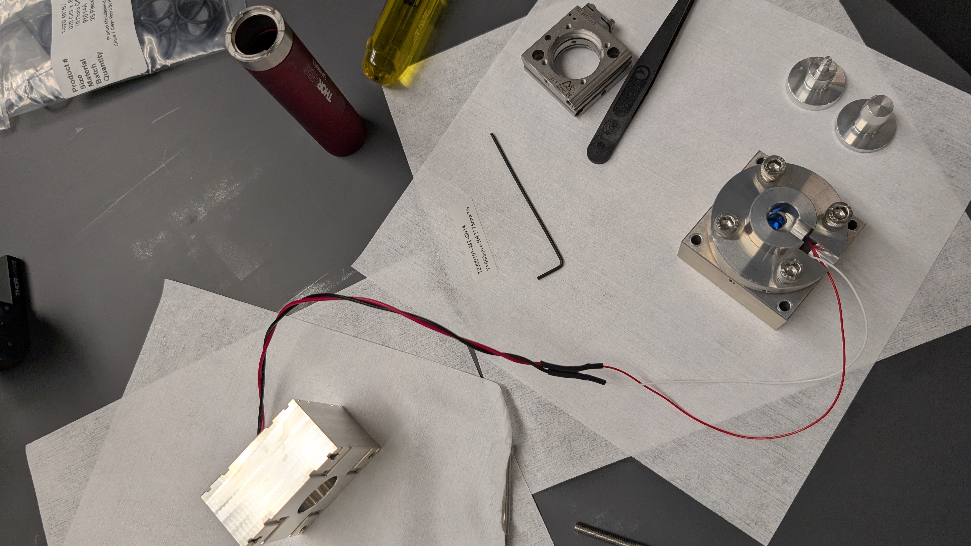
5/16-24 TiCN coated High Speed Steel Taps Cleaned for use around UHV
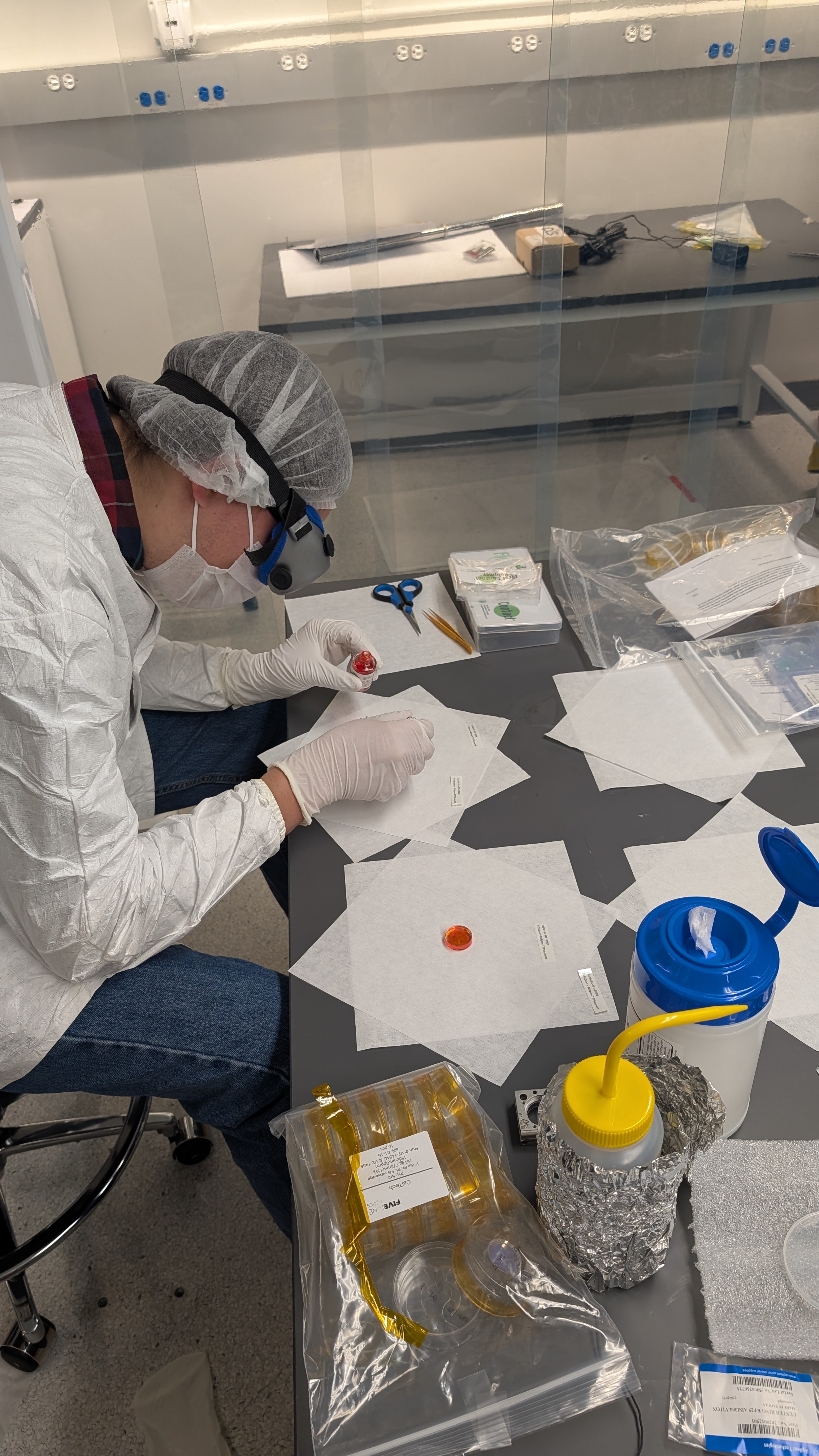
I cleaned some 5/16"-24 TiCN coated High Speed Steel Taps for use around UHV. These taps are stronger and more durable than the taps in the tap set. I did a 90 second bath and sonication in Simple Green:DI water (1:30) and noticed a few particulates come off (I don't think it's the coating as the coating looked intact, but I didn't want to risk stripping it, hence only 90 seconds). I brushed the taps, washed with DI water, did a 2 minute sonication in a DI water bath, washed with isopropanol, then did a 2 minute sonication in isopropanol.


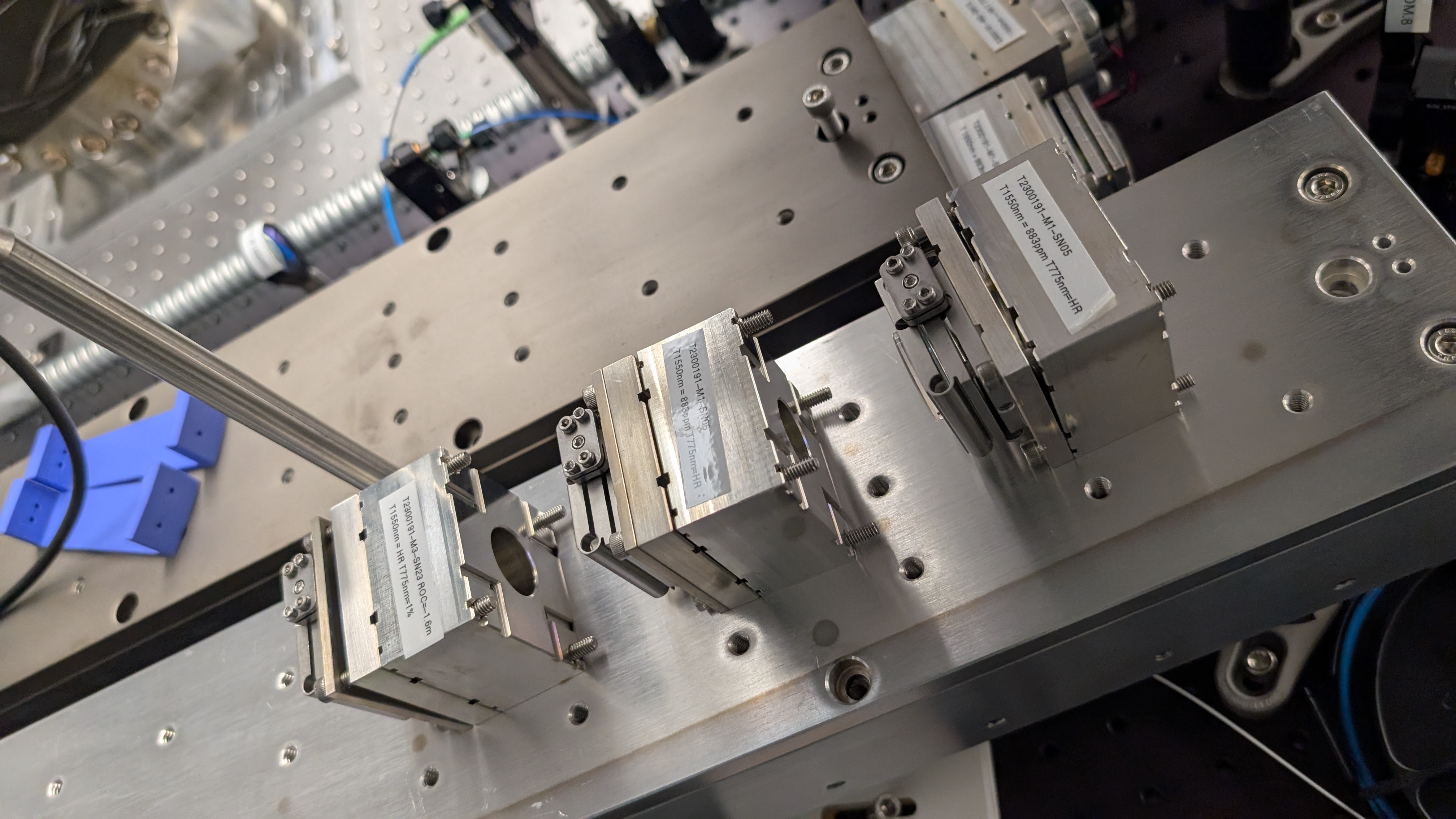
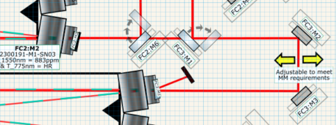
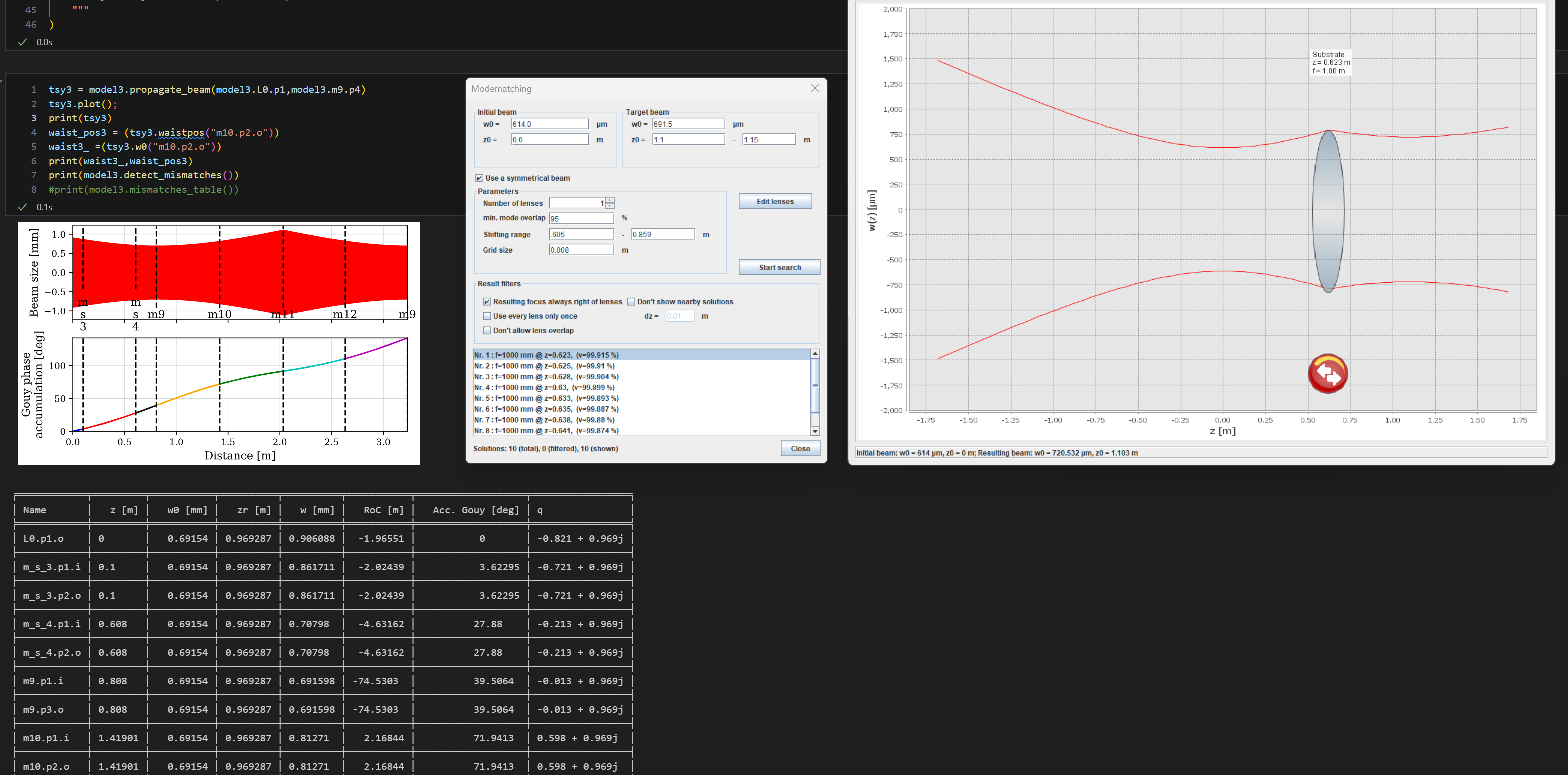
After playing around in JAMMT I found that moving the collimator back would result in easy mode matching solutions. I moved the collimator back 12 inches and reprofiled. Now, according to finesse and JAMMT, a robust solution is f=2000 mm @ z=0.066, f=2500 mm @ z=0.354, (v=100 %). We have these lens. Will implement after lunch.
I put the two lens in the positions according to the above comment. I then profiled the beam after the second lens. This gives the following data below:
Horizontal Vertical
Beam waist radius[um] 402.531593 423.098793
Waist position [m] 0.148341 0.146998
Rayleigh range [inches] 25.859159 28.569197
Radius Average 412.815193
Waist Position Average 0.147669
According to finesse, and accounting for the extra two 1/8 spacers, the beam this cavity accepts is 411 um @ .106 meters after the lens. The measured quanity is 412 um .147 meters after the lens. This should yield a mode mismatch well below 1%. I will close this work for now unless we see large laguerre gauss modes in the cavity scans in the future.