Alex Ramirez - posted 12:17, Tuesday 12 November 2024 (11978)
SNSPD Cryostat Parts Update
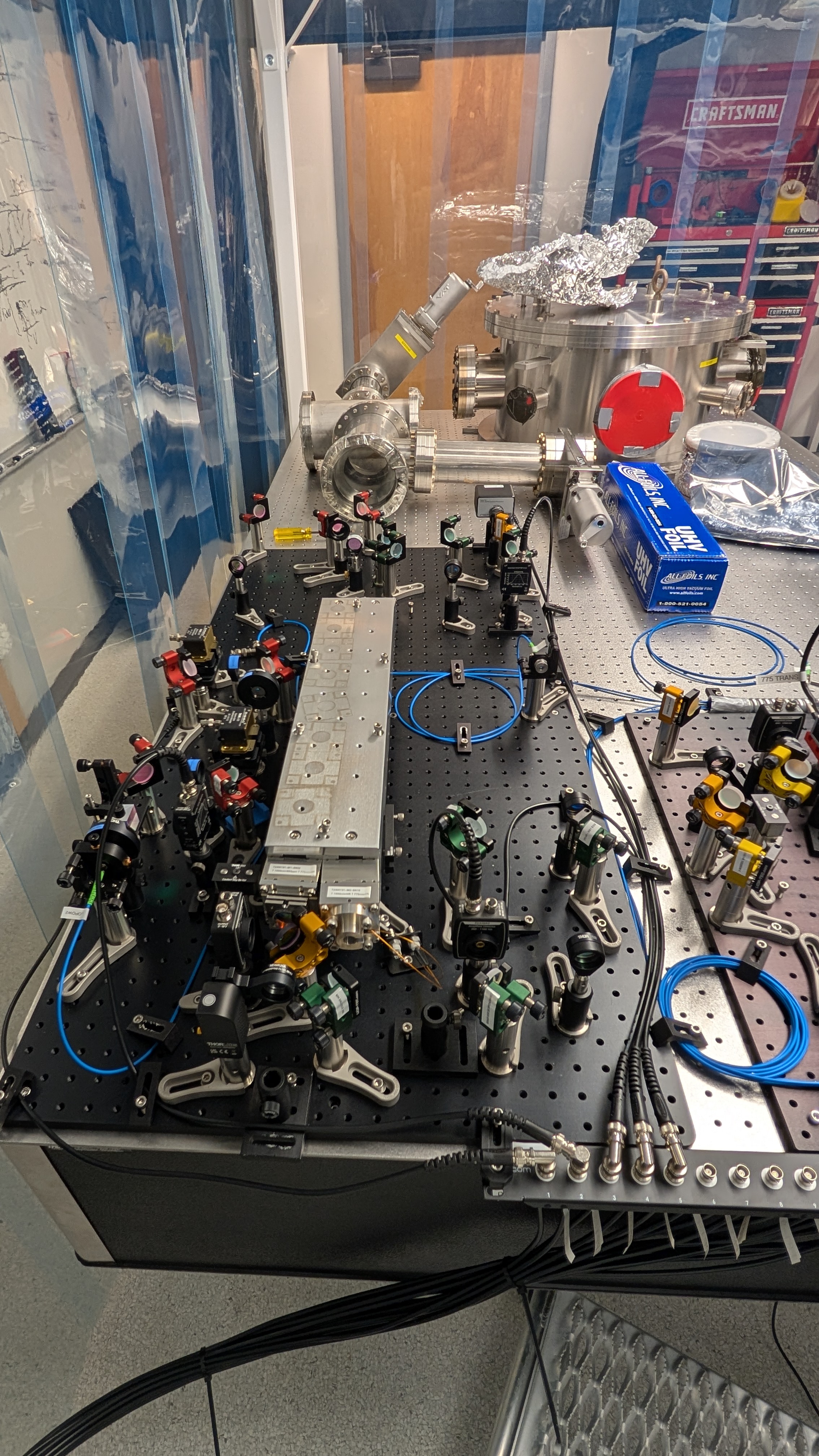
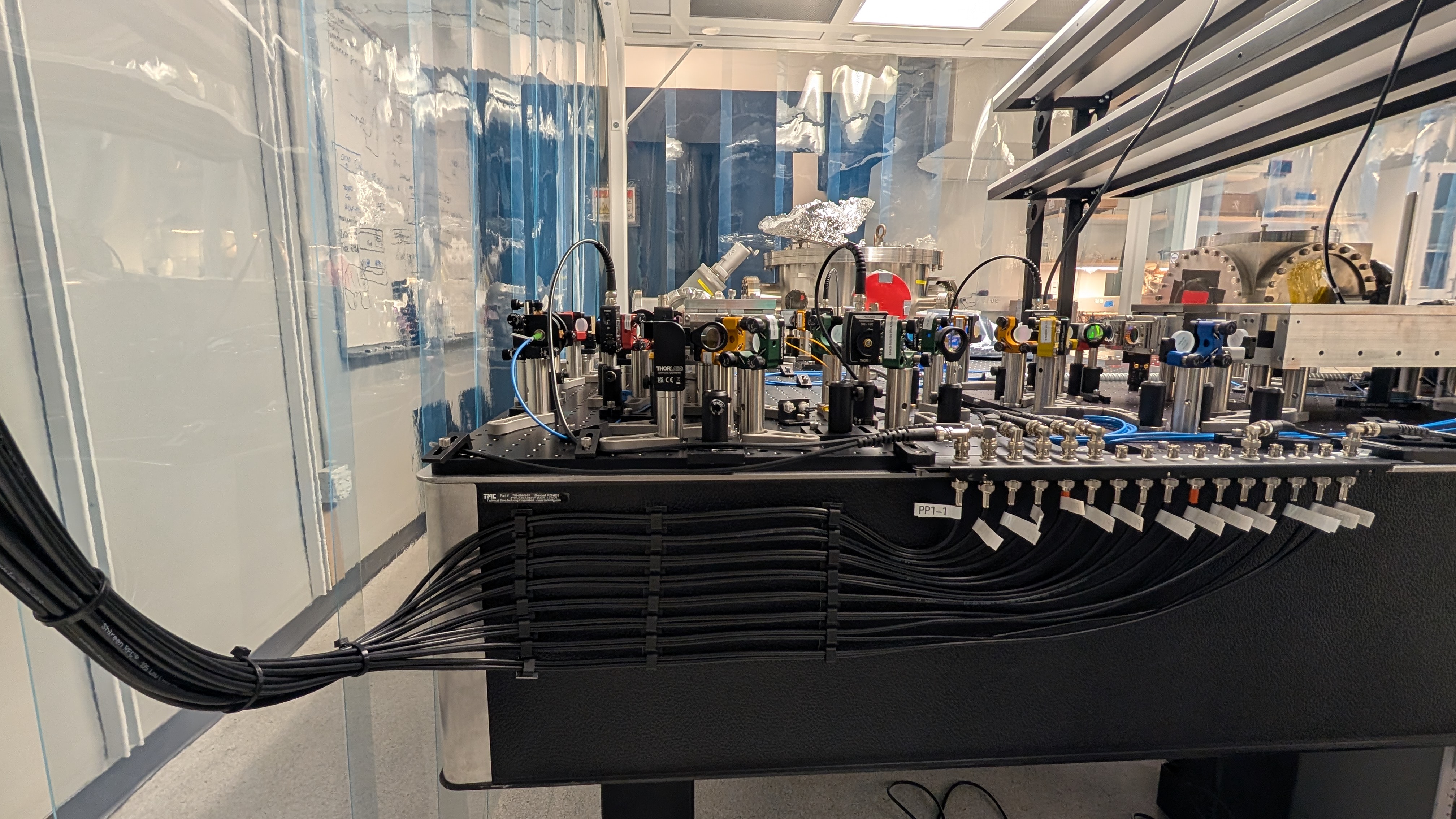
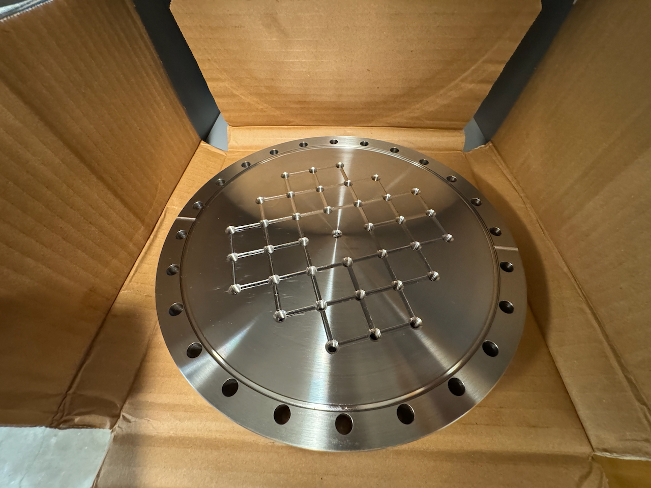
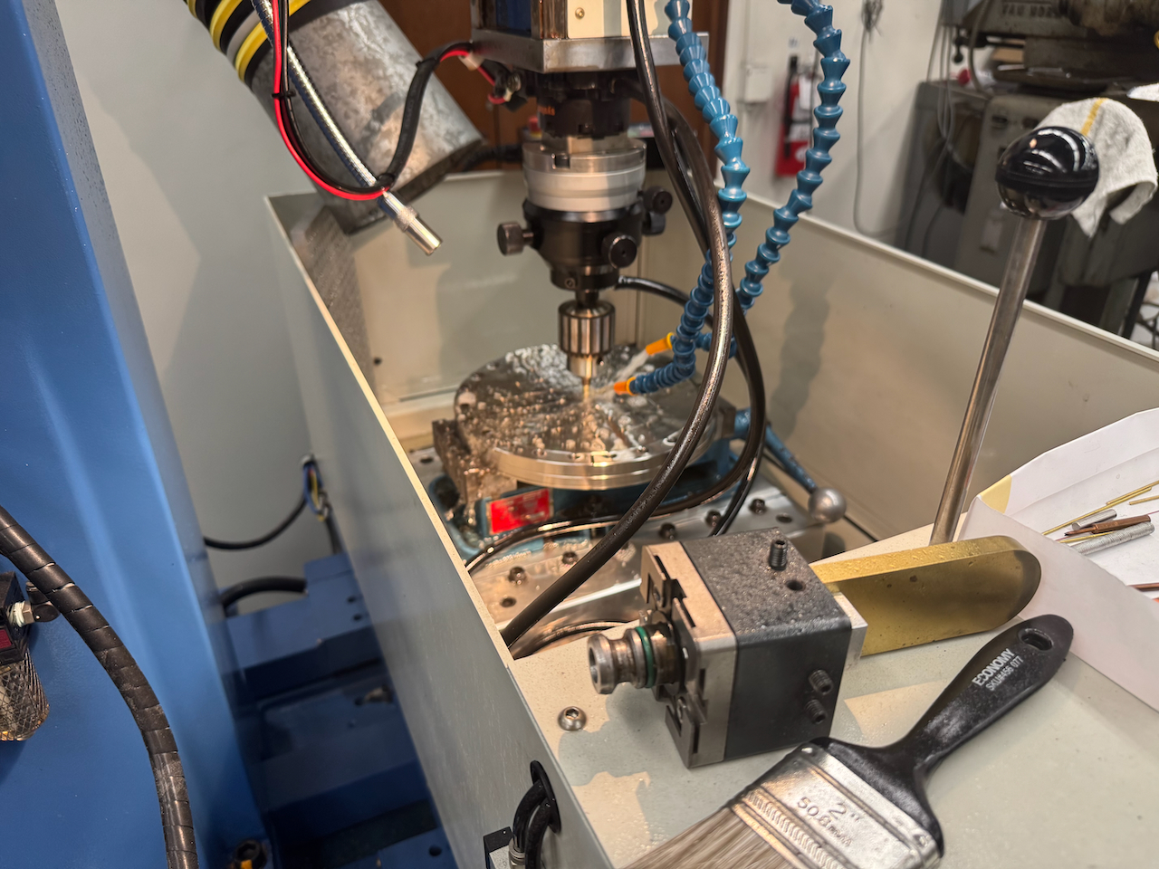
Ioana and I met this morning to go through every stage and component that is needed to operate the SNSPD in the ICE fridge such that we may begin assembling carts for procurement for GQuEST.
Additionally, we will look for off-the-shelf fiber feedthroughs but if not Ioana can assist me in making our own.
The 3 axis stage has also been moved from ICE in Downs to Bridge for testing when we do our first cooldowns on the Dewar. We will look for a replacement for the brass component inside it that expands under cryo.
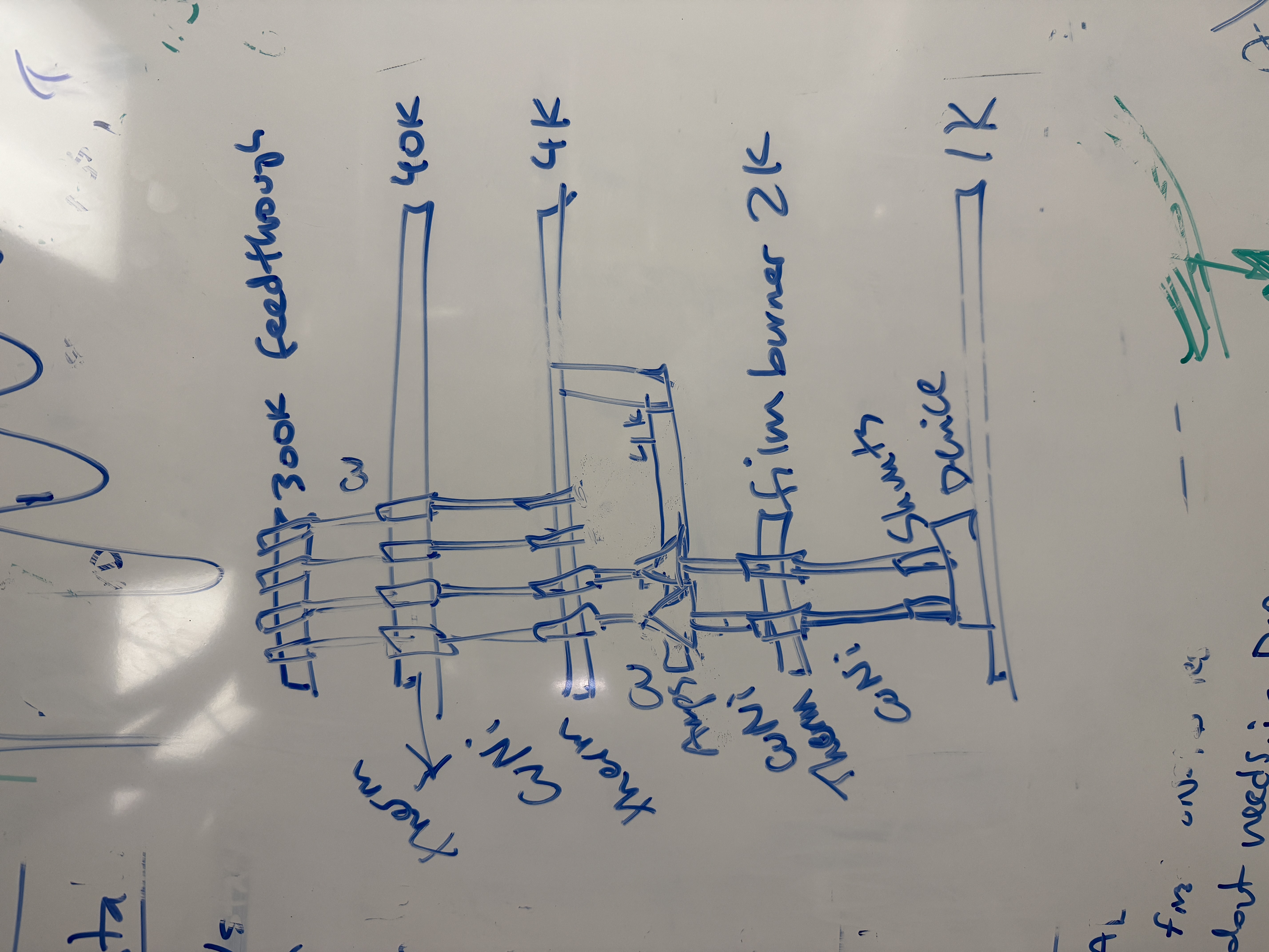
Here is our current list of needed materials and the chain for the signal paths for the SNSPD:
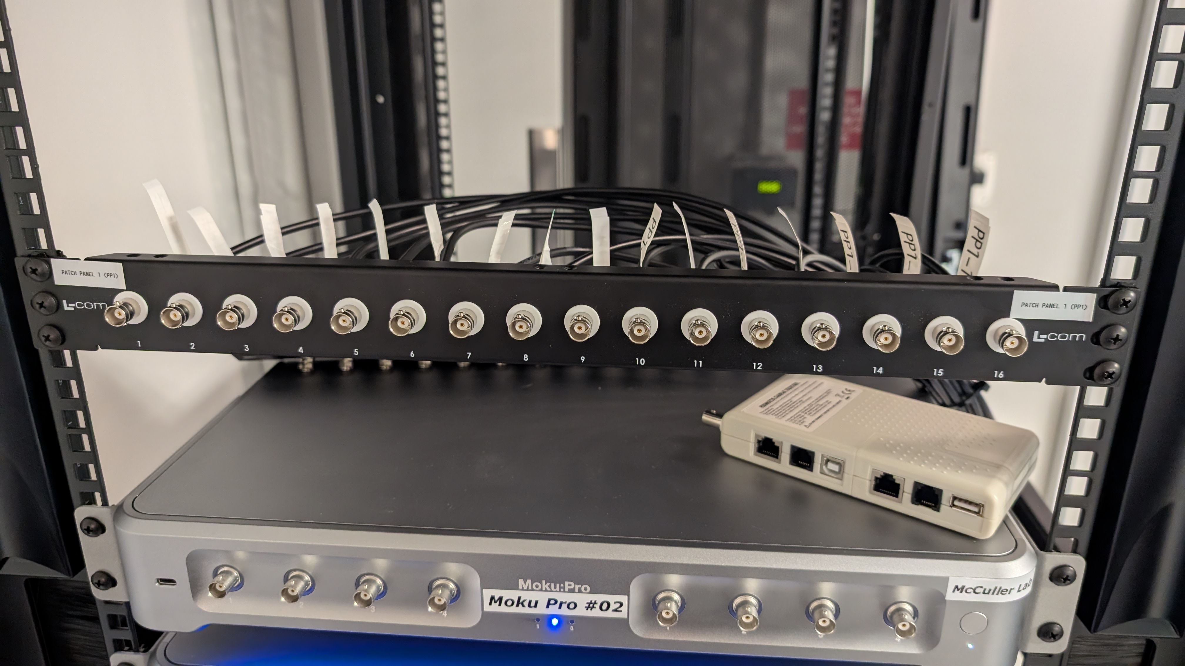
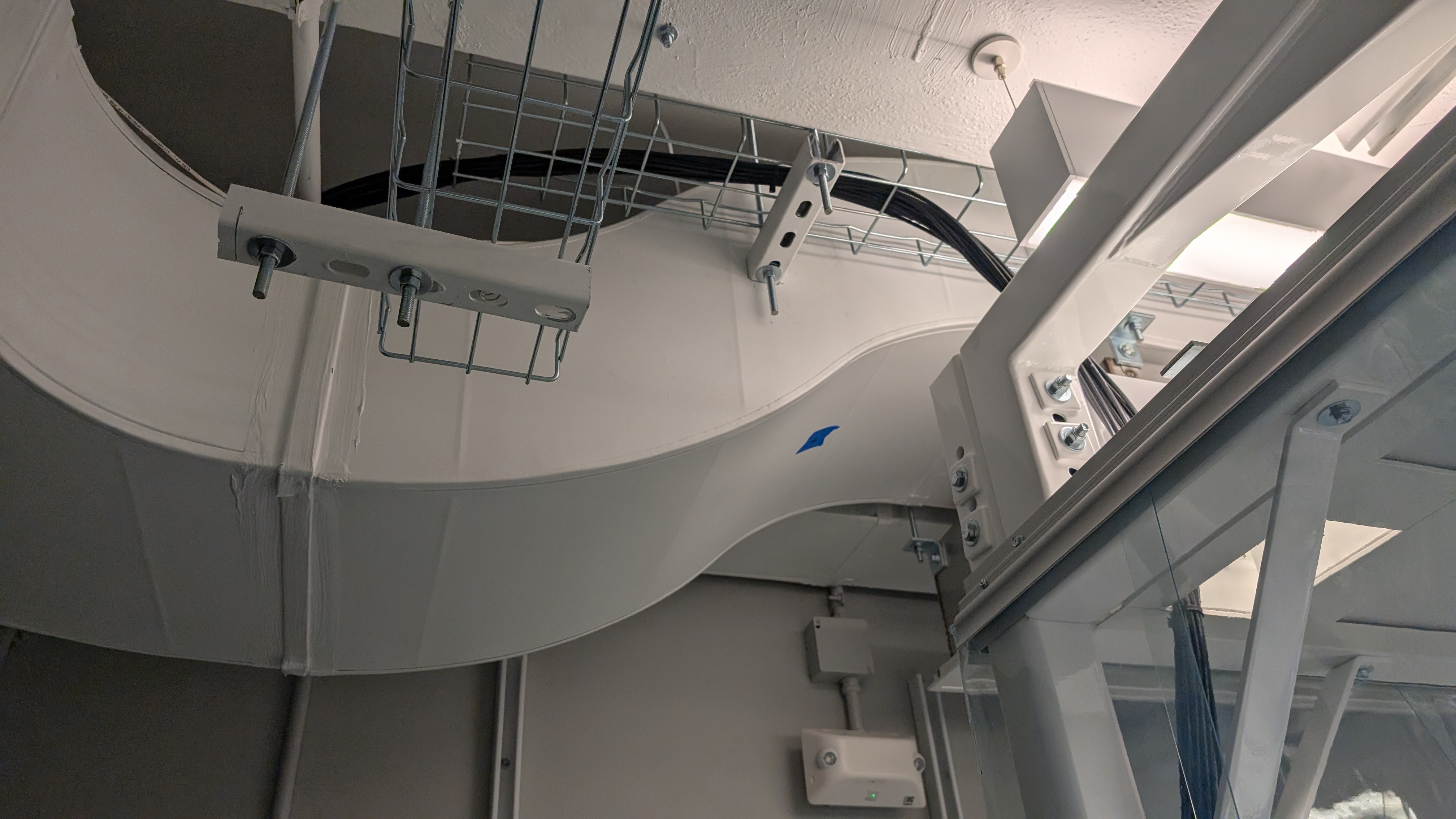
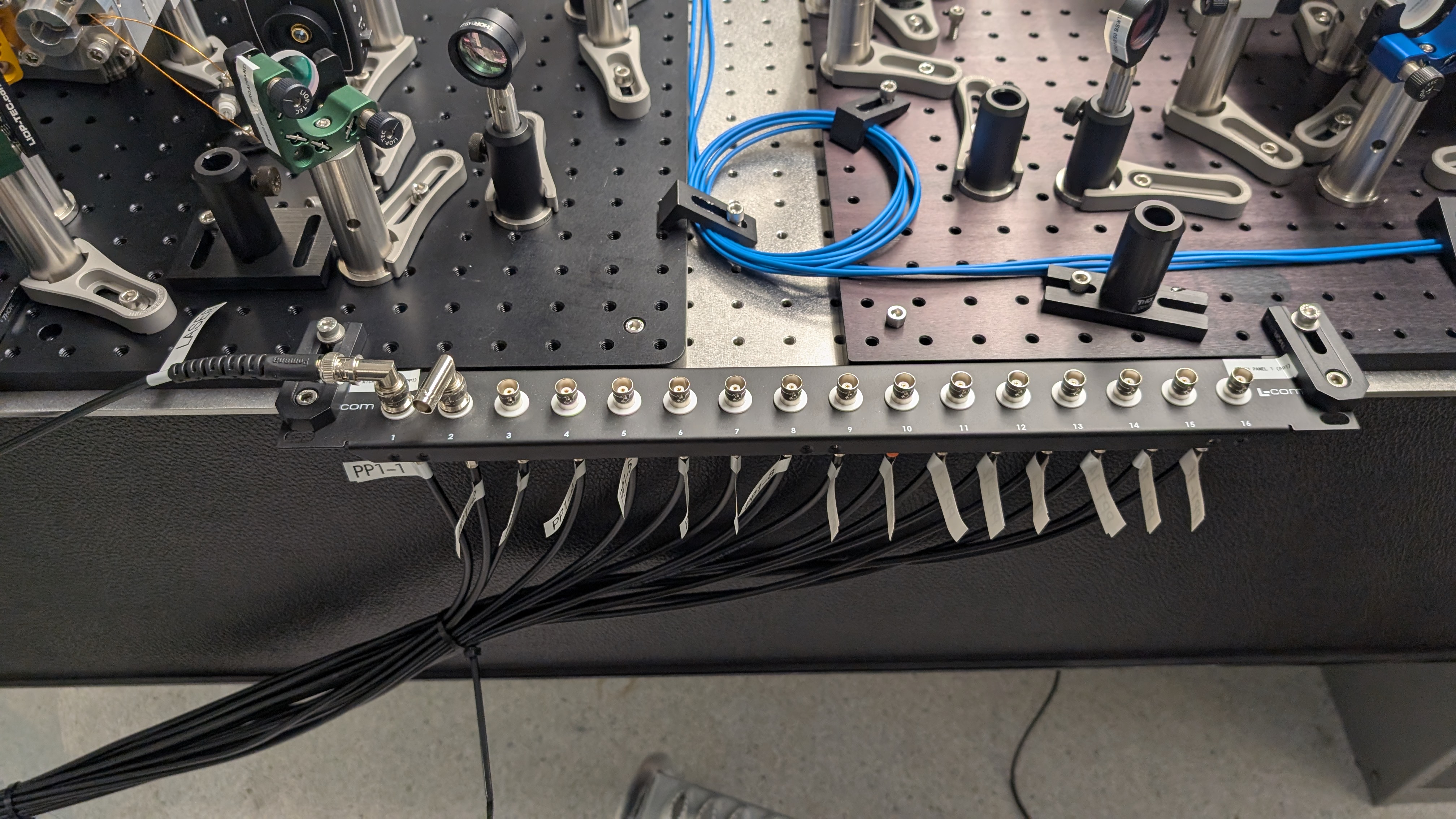
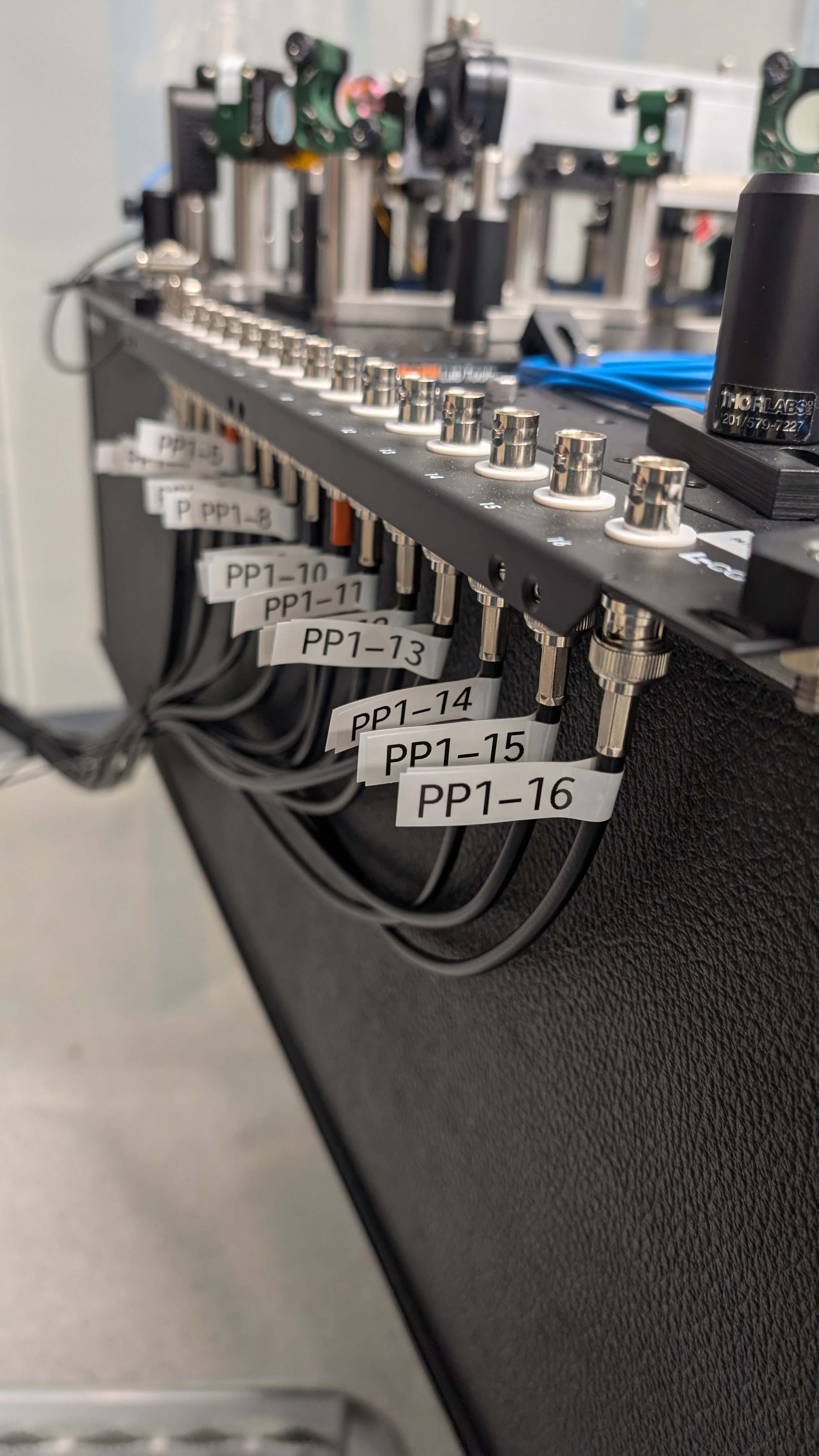
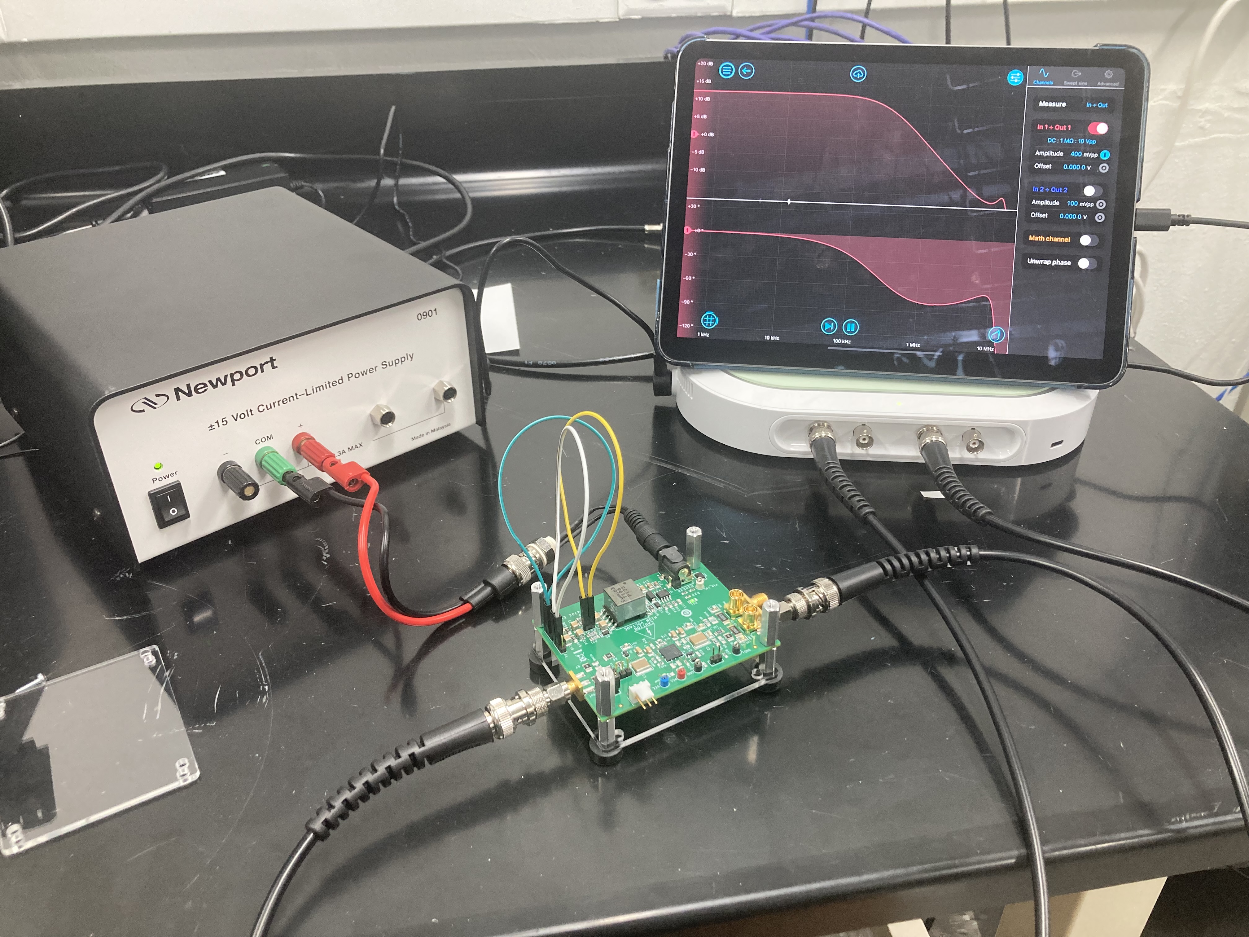
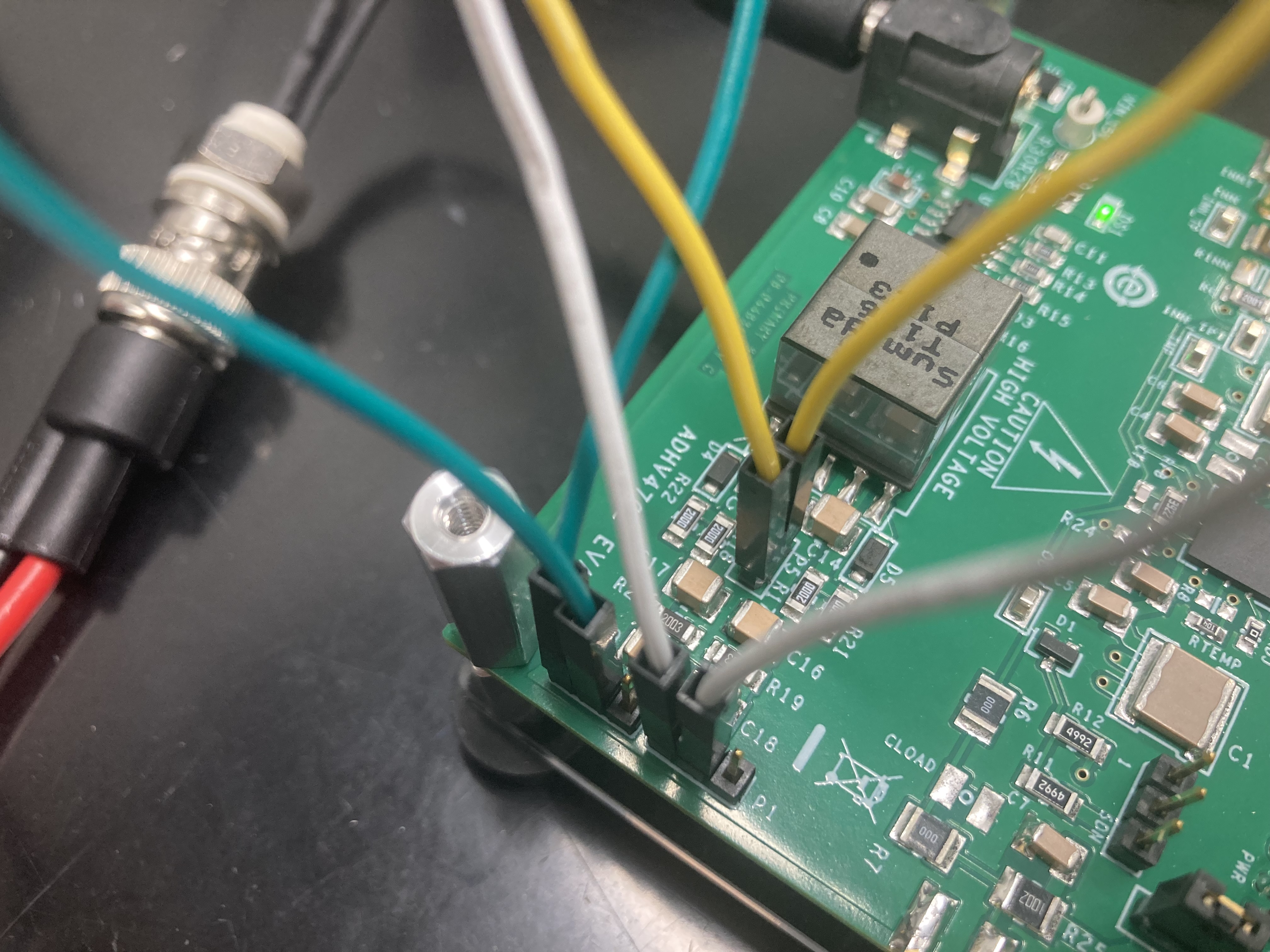
Images attached to this report