Displaying reports 601-620 of 1093.Go to page Start 27 28 29 30 31 32 33 34 35 End
Reports until 22:28, Wednesday 03 July 2024
Atoms General
Briana Chen - posted 22:28, Wednesday 03 July 2024 (11709)
Installed Vapor Cell

[Briana, Ian]

Polarized beamsplitters and fiber couplings are installed and placed generally on the board. Optics needing disassembly (see previous post) have been placed in their correct locations. Still need more BD.2 780 mirrors, which are certainly somewhere. The exact location remains a mystery.

The vapor cell was installed. First, four screws on the bottom of the GCH25-75 heater assembly were unscrewed to separate the structure into a top and bottom. Because the vapor cell is too small to fit in the radius of the heater assembly, adapter rings are enclosed around the vapor cell. The adapter rings were placed on the inner section of the heater assembly due to the length of the vapor cell. The nub on the side of the vapor cell is oriented towards the side to protect the cell. To mount the adapters around the vapor cell, the small screws on the very sides of the adapters were removed to split the adapters into two, after which they were placed over the vapor cell and rescrewed in. For a single adapter, the screws are antiparallel. The set screws on top of the adapters were screwed in last to ensure the vapor cell was fixed in the adapters. The vapor cell was then rotated so that the green part of the screw faced upwards (from the bottom part of the mount). Then, the top part of the mount was placed over the vapor cell such that the upwards-facing green part aligned with the holes for set screws in the top mount. Finally, the four screws were rescrewed in. 

Unfortunately, one of the four screws on the bottom of the vapor cell is now lost in the optical table abyss. The screw type is Black-Oxide Alloy Steel Socket Head Screw, 2-56 Thread Size, 1/4" Long | McMaster-Carr. A replacement was found and used instead. 

Images attached to this report
GQuEST Output Filter Cavities
Ian MacMillan - posted 15:42, Wednesday 03 July 2024 (11703)
Mr Brightside

[Ian, Torrey, Briana, Jeff]

We performed an experiment with the filter cavity. We split off the fast controller error signal going to the laser, and put it in the new Fosi speakers. Then used another speaker to play a song near the filter cavity. The speaker used to play the song was physically decoupled from the table and cavity. We then recorded the output signal using the moku data logger (original file found at "Nextcloud/GQuEST/B102/Bright.csv"). We then wrote a quick script that turns a CSV into a .wav file. Bright.wav is the result. 

Mr. Brightside can be clearly heard. Joking aside this is actually show casing the strong audio pick up of these very long bowtie cavities. The constant tone in the .wav file is a 840 Hz tone that is a result of poor grounding to the DC modulation input port used to control the frequency of the laser.

This is the way music like this was made to be heard.

Non-image files attached to this report
GQuEST General (GQuEST)
Daniel Grass - posted 14:20, Wednesday 03 July 2024 (11708)
Holder for the GQuEST End Mirror Wavefront Adjustment Subassembly

The design for the GQuEST End Mirror Mount ultimately puts the wavefront correction subassembly on 4 piezos to lock CARM and DARM. These piezos go to a custom end mirror mount from Siskiyou.

In the mean time, we want to mount this subassembly by itself to image the wavefront. I designed and made a part that can mount it on a 1/2 post, 1" post, or PY005 via a tapped #8-32 hole or #8 through hole.

See attached files

Non-image files attached to this report
Atoms General
Briana Chen - posted 10:33, Wednesday 03 July 2024 - last comment - 13:06, Wednesday 03 July 2024(11705)
Weird fiber collimator packaging

One of the 650-1050 nm CFC5A-B fiber collimators (new) from Thorlabs does not have the front yellow covering on it. The one that did not have the covering (left in picture) is labelled #1 on top of the mount. 

Images attached to this report
Comments related to this report
Lee McCuller - 13:06, Wednesday 03 July 2024 (11706)

That is just protective Kapton tape. It will work just fine. It may just be a little more dusty than it should be. You can try the new football-shaped air puffer on it.

Atoms General
Briana Chen - posted 22:56, Tuesday 02 July 2024 (11704)
SHG/Vapor Cell breadboard

[Briana, Ian, Torrey]

On SHG setup, all optics (including beam dumps and lenses) except the waveguide are temporarily put in place (not aligned). It is slightly cramped so we may need to switch to a bigger board. 

Moved the vapor cell scheme onto the 1.5 ft by 2 ft breadboard, which was previously adjacent to the 2 ft by 2 ft breadboard. The 1.5 by 2 is now where the 2 by 2 breadboard was and the SHG setup moved to where the 1.5 by 2 breadboard was. Items on the 1.5 by 2 were cleared off/returned to their labelled drawers and certain optics (three next to the vacuum component on the side towards the computer) will be disassembled and returned to the drawers since they are not in use. The vapor cell scheme can fit on this breadboard (see new schematic). We are in need of 4 more 780 nm mirrors, which already have a quote in. General object locations have been marked on this board. The fiber couplings will be mounted alongside other optics in the vapor cell schematic tomorrow. The 2 ft by 2 ft breadboard has been placed somewhere (I don't know where but would guess in the left corner of the lab near the giant materials tray drawer- this may be a question for Ian).


Images attached to this report
Lasers General
Torrey Cullen - posted 10:57, Tuesday 02 July 2024 (11701)
1560 nm, 2W laser for RBQ experiment.

https://dcc.ligo.org/M2400207

Non-image files attached to this report
GQuEST General (GQuEST)
David Nguyen - posted 09:24, Tuesday 02 July 2024 (11700)
Magnitude Bode Plot Slopes Follow Up
The first plot I attached is a logarithmically scaled gain plot for a lowpass filter with corresponding slopes for different critical frequencies. As we see, the filters retain the -40dB/decade slope as expected, and I speculate that the incorrect slopes from my previous post resulted from sampling points too close to the critical frequency. The second (and third) plot is a gain difference plot between the float filter and lower bit resolution filters. I have also included selected points for verification of these differences. They result from manually inputting tones into the filters and finding the gain using the Welch method. The third plot has the 38 bit resolution toggled off to show that 38 bits produces the same precision as 39. My next post should be about how differing bit resolution affects digitization noise.
Images attached to this report
Lasers General
Jeffrey Wack - posted 18:11, Monday 01 July 2024 (11696)
ULN15TK laser DC voltage control calibration

Here are some calculations regarding the DC control of the frequency of the Thorlabs ULN15TK laser in B102. The measured value of the Hz/V laser tuning coefficient disagrees with the value calculated from the datasheet by roughly a factor of 2.


First, the laser frequency was swept with a 2Vpk-pk triangle wave at 10Hz. Two resonance peaks were identified to be 30ms apart. We want to convert this time difference into a voltage difference using the properties of the tringle wave.

30ms*2V*2*10Hz = 30ms*40V/s = 1.2V

The free spectral range of the cavity, measured in Hz is the inverse of the travel time in the cavity, or c/L

FSR = 3e8/2.4 = 125MHz

Together these values give 104MHz/V


We should also be able to calculate this value (Hz/V) using only the datasheet of the laser.

Under the specs tab, it is reported that the DC voltage to current conversion rate is 2 mA/V, and the current tuning coefficient is 0.25pm/mA

This gives us 0.5pm/V tuning. We now convert this to frequency.

0.5pm/V*(3e8m/s)/(1550nm)^2 = 62MHz/V


Atoms General
Briana Chen - posted 17:55, Monday 01 July 2024 - last comment - 11:29, Monday 26 May 2025(11699)
New SHG Setup

[Briana, Ian, Torrey]

Placed the SHG setup on a new 1 by 1.5 ft breadboard (see new schematic). We will separate the SHG and vapor cell setup to be on two different sleds since they are fiber coupled and can be easily put in place elsewhere. The beam dumps are not in place and the optics are not aligned yet. Replaced Torrey's five 780 nm mirrors with the ordered 780 Newport BD.2 mirrors. Assembled the second Faraday isolator for the 780 nm light. We will not need to use the 1550 nm mirror that has the piezo imprint since the new schematic reduces the number of 1550 nm mirrors needed from 4 to 3. 

Images attached to this report
Comments related to this report
Briana Chen - 11:29, Monday 26 May 2025 (12324)
Images attached to this comment
GQuEST Output Filter Cavities
Torrey Cullen - posted 16:57, Monday 01 July 2024 - last comment - 12:17, Tuesday 02 July 2024(11697)
filter cavity 2 initialization

According to "C:\Users\gques\Nextcloud\GQuEST\Layout_Mockups\readout_FCs_1_2_and_3.svg" I'm estimating for one cavity we need the following items below.
1550:
-5 HR/mount
-Flip Mount
-Fiber output coupler - DONT HAVE
-1550 fiber
-1550 Fast
-1550 slow PD 
-1550 BS - have
-Lens for MM
-posts/forks x10

775:
-5 HR/mount 
-775 Fiber output coupler x2 
-775 long fiber 
-775 BS 
-775 Fast 
-775 slow PD 
-posts/forks x10
-2 lens for MMing cavity

I have gone through the supplies and found everything on the list and placed them on the optics table (see attached photo), except for 1550 fiber coupler. We do not have enough of these items for a second (3rd total) filter cavity to be built. I am just getting this ready so I can order anything we don't have and immediately need for progress to be made after I get back from 4th of july break. We will need to do another large order to start progress on the 3rd filter cavity.

Additionally, I currently have Ian/Briana's fast 775 PD set aside to be FC2 REFL PD. When you guys are ready for one please take the one in transmission of the first filter cavity. 

For the placement of the new sled that should arrive on Wednesday, I am planning on placing it cattycorner to the existing 2x4 on the same optics table. They can't be placed side by side without a bit of overhang. I have cleared this space already. Please do not place new optics here as they will quickly need to be moved. 

Images attached to this report
Comments related to this report
Torrey Cullen - 12:17, Tuesday 02 July 2024 (11702)

All optics have been mounted and labelled. After mounting these we are completely out of 775 HR. Will add this to the order.

Controls Optimal Controls
Ian MacMillan - posted 15:52, Monday 01 July 2024 (11694)
Optimal controller for GQuEST piezo laser lock and buzz

[Ian, Jeff]

Jeff and I used the models for the previous fitting of the laser lock in the piezo controllable cavity to create an H2 optimal controller. We used two FOMs that were flat giving us no relative scaling.

The models we used for the plant and for the noises are either out of date or wrong. Jeff is working on getting better models as well as automating the system to take the data.

The current configuration (provided in the PLC folder of buzz) solves for the H2 but does not solve for the H infinity bounded (Hib) controllers. For the Hib controllers it seems like the solver is solving, i.e. it does not return an error, but the list of results is empty. I am not sure why this is true. I have not investigated very thoroughly for this problem.

The H2 solver seems to work but returns a controller with a DC amplitude of 10^10. I attached a figure (H2_controllers.pdf) with the hand tuned controller and a scaled down version to fit the requirements of the Moku Pro. Note that this controller is made with the wrong noise and plant and would need to be updated. It is not to be used in the system. The controller's order 50 so would need reducing even if it were to be used. When I was scaling the controller down, I decided to scale it down before the compute.calcFullResults(). This means that all of the loops frequency responses and RMS values were updated for this new controller. With the scaled down controller, i.e. the H2_optimal_controller * 1e-5, the RMS value improved by two orders of magnitude. This should be impossible. The H2 optimal controller should have the lowest possible RMS. Nothing I could do to the H2 optimal controller should be able to decrease its RMS.

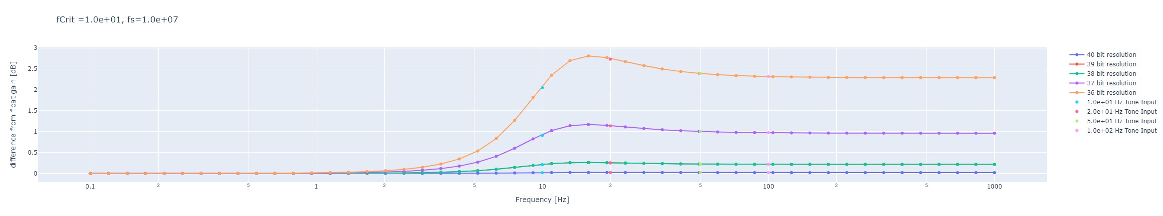
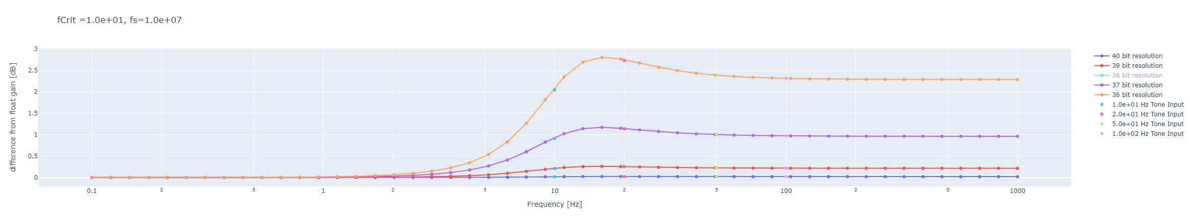
To trouble shoot this I started to look at the connections for the composite state space model I made. I noticed that in the connections when I used .siso() to pull out a component system from the larger system, it would not match the original, i.e. S would not equal sys.siso('S.out', 'S.in'). These two things should be equal or almost equal the very lest. I reduced this system to just the environmental noise, which I am calling S, and the plant, which I am calling P. When I connected them in series with the function ssutil.multiconnect() I got different results depending on which order I gave it S and P. Note: multi connect takes a list of systems as its first argument (whose order should not matter) and list of connections to make in the system. when I changed the order of the systems in the system list (giving it the lists [S, P] or [P,S]) I saw different results for the frequency response when I broke them apart. with both orders the connections were the same only the order of the provided systems was different. In the attached fig (Connection_order.pdf) it can be seen that the S from the [S, P] ordering does not agree with the S that was used to make it. Normally I would assume that this was some error in the type of the system, i.e. I used the wrong convention when making a ZPK, but these two systems were made from the same S and P model so they should only be different in the order they were given. 

These should be the same and bug like this could affect other models. To debug I looked at the connection functions and played around with the order that I provided the systems in the makeSPOFF() function. I looked at how I was assembling. I just used controls append function to make a big system with all of the all of the sub systems that were not inter connected. Then used the interconnect function in control to connect them all. The most obvious error would be that the indices were messed up according to the order in which the systems were presented. But this would have probably shown up by now. In any case I checked this and it seems to be correct. I looked at the bode plots for all of th indices and they seem to be referring to the same thing. It is possibly some scaling issue. But I haven't figured it out yet.

Non-image files attached to this report
Lasers General
Torrey Cullen - posted 14:32, Monday 01 July 2024 - last comment - 17:10, Monday 01 July 2024(11692)
780 SOP

Thorlabs 780 SOP for the RBQ experiment.

https://dcc.ligo.org/M2400206

Non-image files attached to this report
Comments related to this report
Lee McCuller - 14:26, Monday 01 July 2024 (11693)

Why only upload the final document. If you upload the sources, one day others will write SOPs.

Torrey Cullen - 17:10, Monday 01 July 2024 (11698)

I've updated the 1550 SOP to include accurate start up instructions.

https://dcc.ligo.org/M2300159

Atoms General
Briana Chen - posted 10:06, Saturday 29 June 2024 (11690)
More SHG prep

[Briana, Torrey, Ian]

Decided the dichroic beamsplitter should not be flipped with the mirror because of potential back reflections in the 780 nm mirror from the 1550 nm light coming out of the crystal (schematic was reverted). Learned to do basic mode matching. We used the Nanoscan Photon beam profiler to measure the beam size (placed on the breadboard right next to the 2 by 2 breadboard) by measuring the mean 13.5% (intensity decayed to 1/e^2) beam waist (diameter) along the x and y axis at 5 different distances from a reference point (in this case, the mirror right before the lenses/crystal in the schematic). Then, Torrey's beam profiling code fit the datapoints to a Gaussian beam profile and output the location of the waist. The JamMt software was used to determine the location of the beam waist and the effect of lenses on beam size. The waist was ~13.4 inches (in beam path length) before the reference point mirror, so the waist would have been located approximately at the immediate exit of the laser. The internal laser lens was not adjusted. The beam profile and the numerical aperture from the crystal's specs (WG-1560-40) will determine whether the focal lengths of the lens are adequate. We will redo setup/alignment/beam profile measurements when the 1560 nm laser is put in place of the 1550 nm laser. Also, we found the ordered 780 nm mirrors so we will replace the 780 nm mirrors currently in use.

Images attached to this report
GQuEST Output Filter Cavities
Torrey Cullen - posted 16:42, Friday 28 June 2024 - last comment - 12:45, Monday 01 July 2024(11689)
1550 ringdown update

Using the PDH error point offset (~5 mV) and the output offset (100s of mV) as the kick point seems to kick the laser frequency in a way that is creating some non-linearities so that the data never matches up with the expected decay function. I've found a way that seems to get around this. Locking the cavity and shifting the output offset by 10 mV breaks the lock long enough to see a decay. I think the take away here is we need a more consistant way to fast shutter the 1550 light going to the cavity.

Attached is a fit a plot showing the fit to the decay envelope, the full REFL, and the full TRANS signal with the corresponding finesses from these fits. I am unsure at the moment which one should be interpreted as most accurate, although I'm leaning towards the REFL envelopes. 

I've taken 5 more of these measurements to average over. Will process these monday morning.

Images attached to this report
Comments related to this report
Torrey Cullen - 12:45, Monday 01 July 2024 (11691)

Attached is all 5 trials using this method. Separated by type of fit/measurement.

Images attached to this comment
GQuEST Output Filter Cavities
Torrey Cullen - posted 16:10, Friday 28 June 2024 (11688)
Ghost Beam on 775 Path

[Briana, Torrey]

The ghost beam that shows up on the 775 camera is coming from the beam splitter that splits the cavity transmission light onto a PD and camera.

Displaying reports 601-620 of 1093.Go to page Start 27 28 29 30 31 32 33 34 35 End