[Daniel, Torrey]
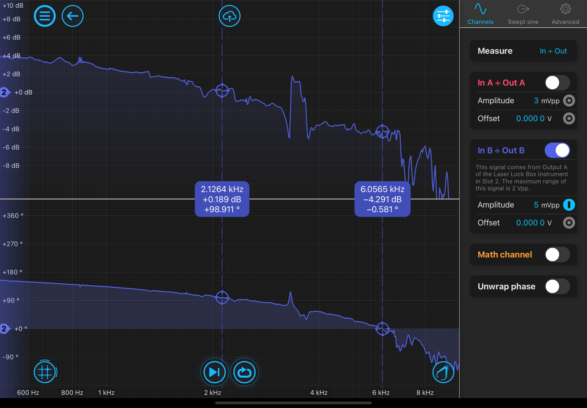
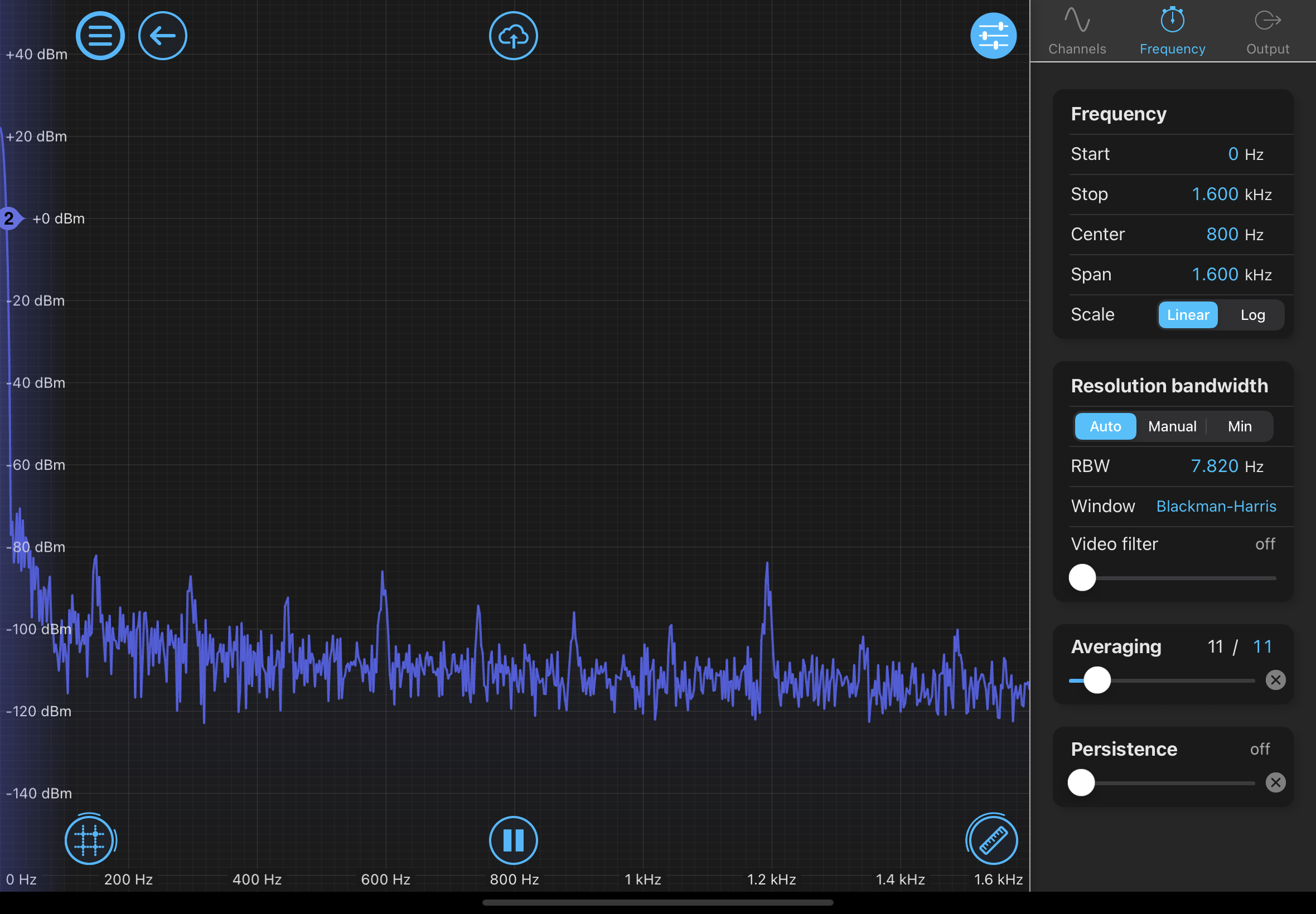
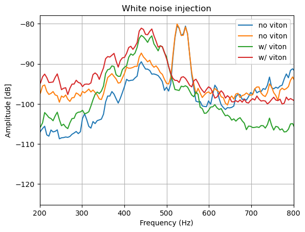
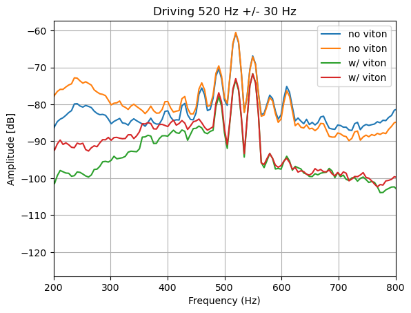
We replaced the Noliac NAC2125-H08 piezo with a Thorlabs PA44M3KW to see if it changed the UGF. Everything else stayed the same physically, the control loop of the slow controller was shaped to optimize lock quality. The UGF went from 1 kHz to 3.5 kHz. Visibily the lock seems much more stable. I think it is worth testing difference stiffnesses of the viton o-rings in the piezo mirror set ups (the piezo pushes into the viton o-ring to change the length of the cavity).
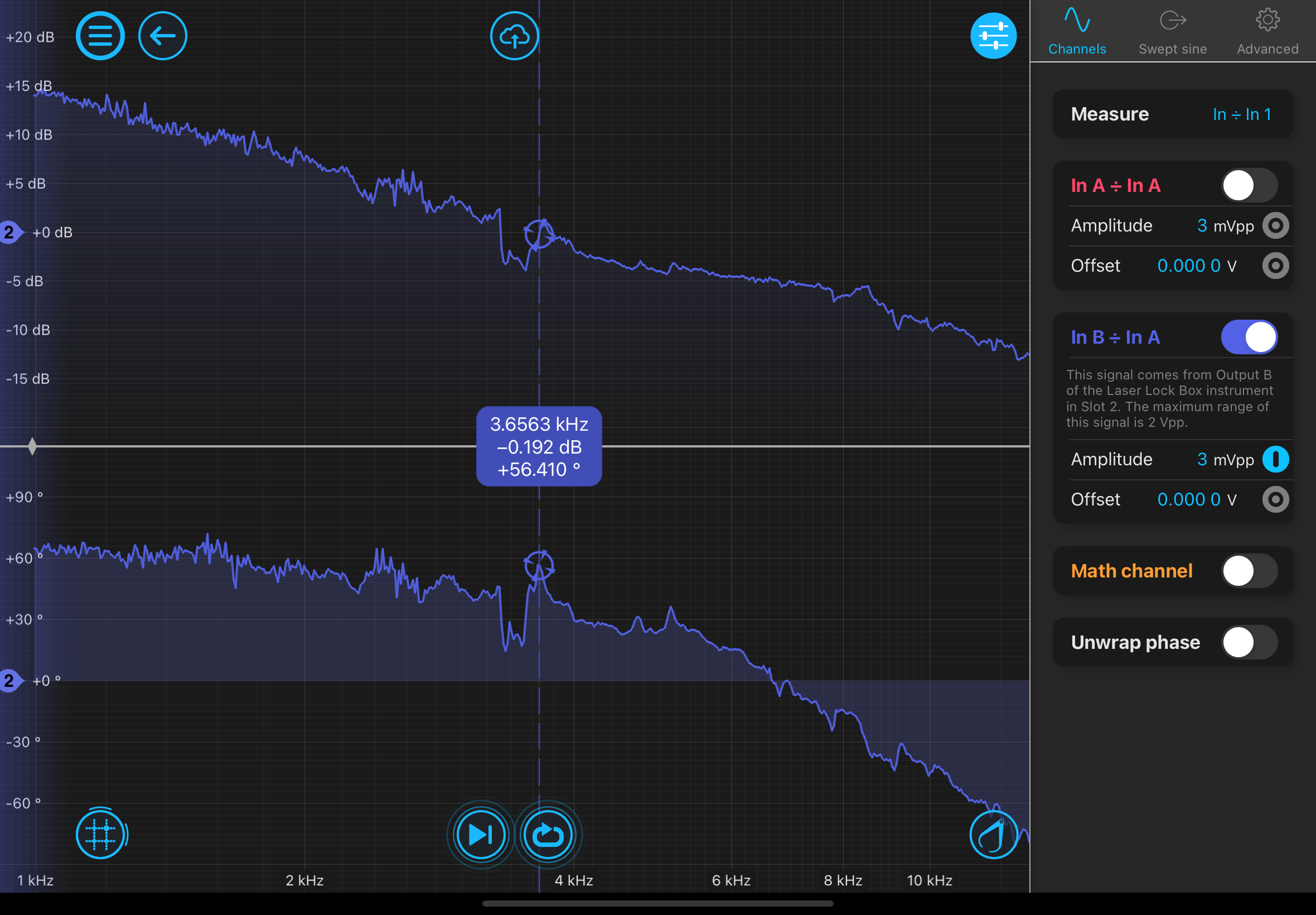
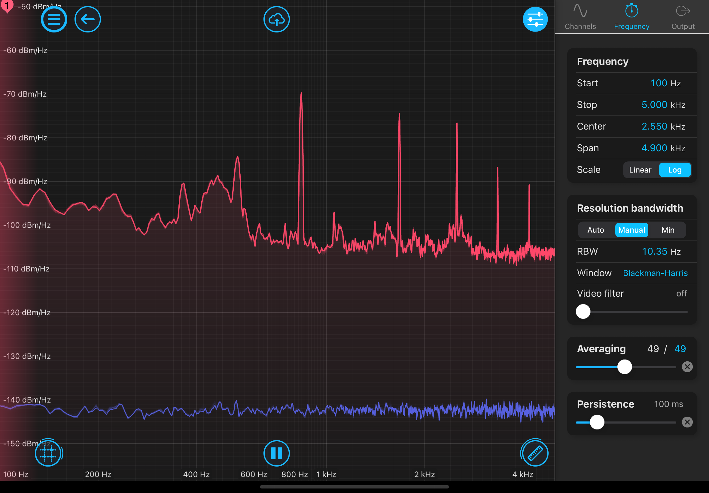
There seems to be a feature at ~3.3kHz that can be seen in the open loop transfer function as well as the error signal in the laser lock box (in the error signal at least when a bad controller loop shape is given). Potentially some resonance of the piezo? Adjusting the tightness of the SM1 ring does not seem to move this feature.