[Daniel, Sander]
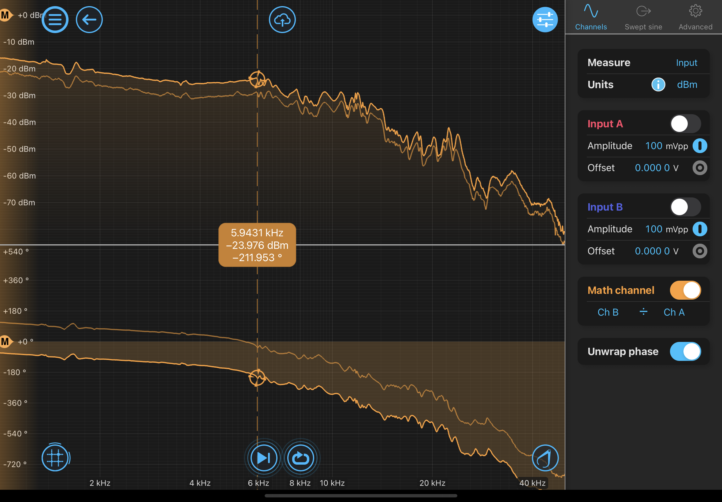
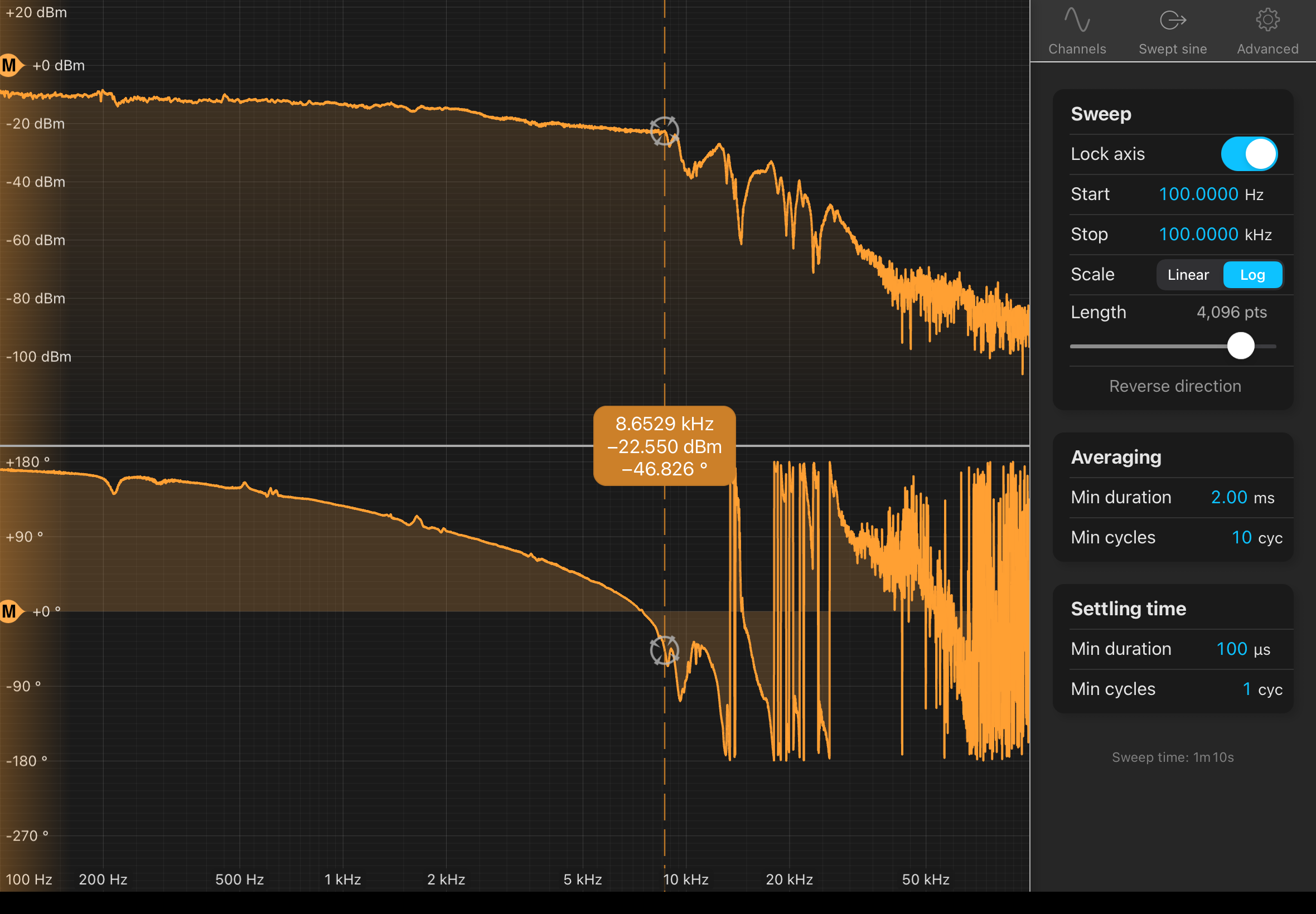
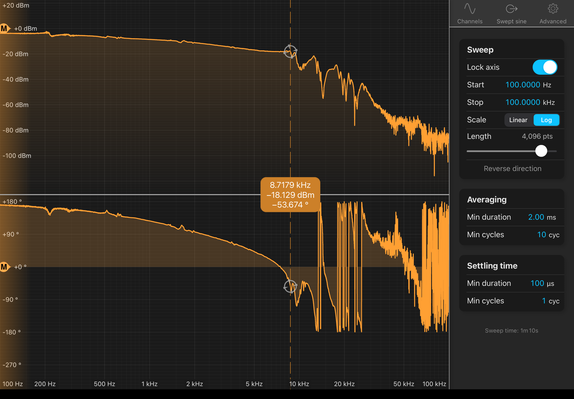
Using the Moku:Pro, we measured the (open-loop) transfer function of the mounted ring piezo mirror actuator in a Michelson interferometer. The piezo-mirror assembly seems to have a fundamental resonance at around 8.7 kHz.
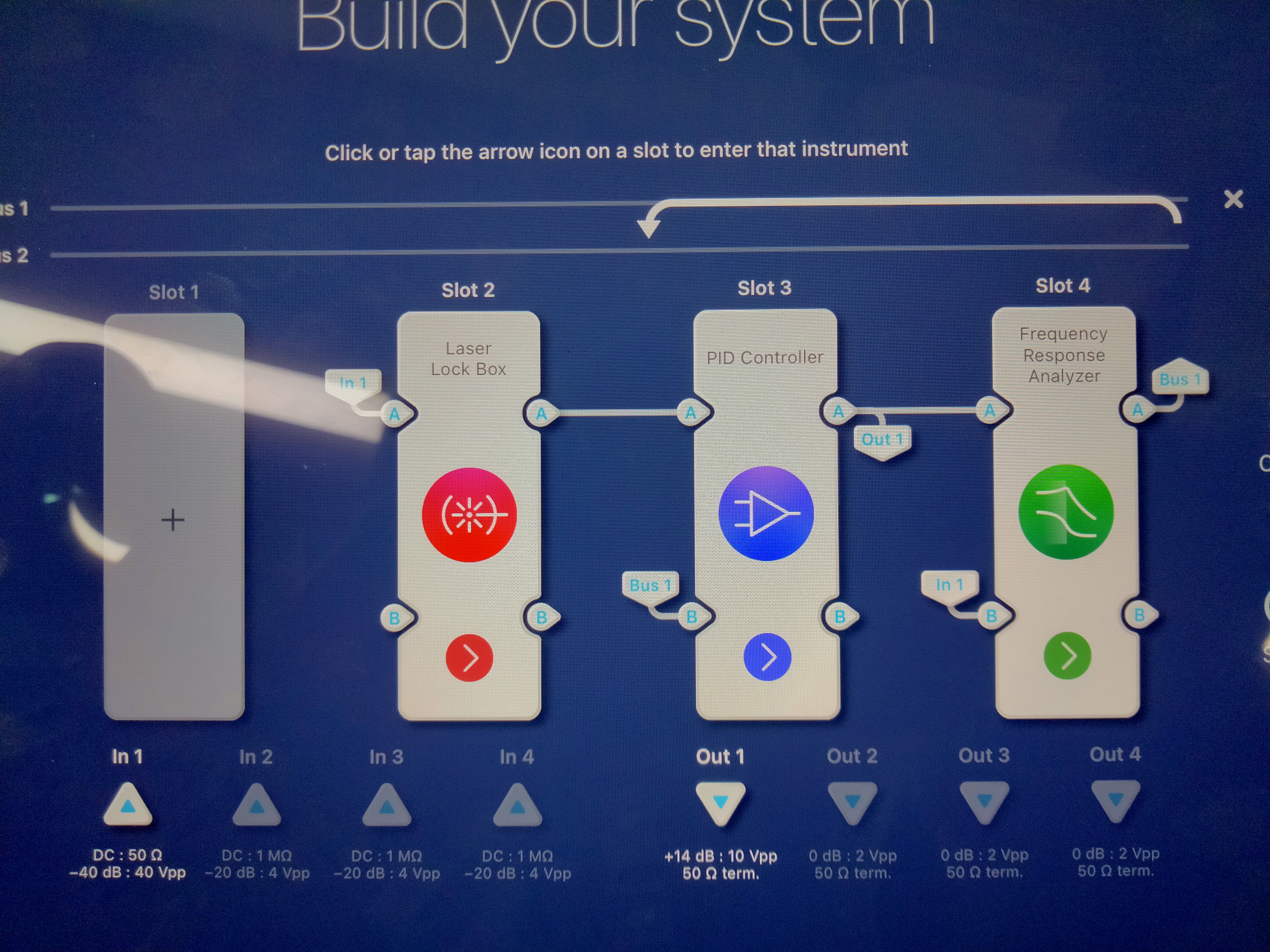
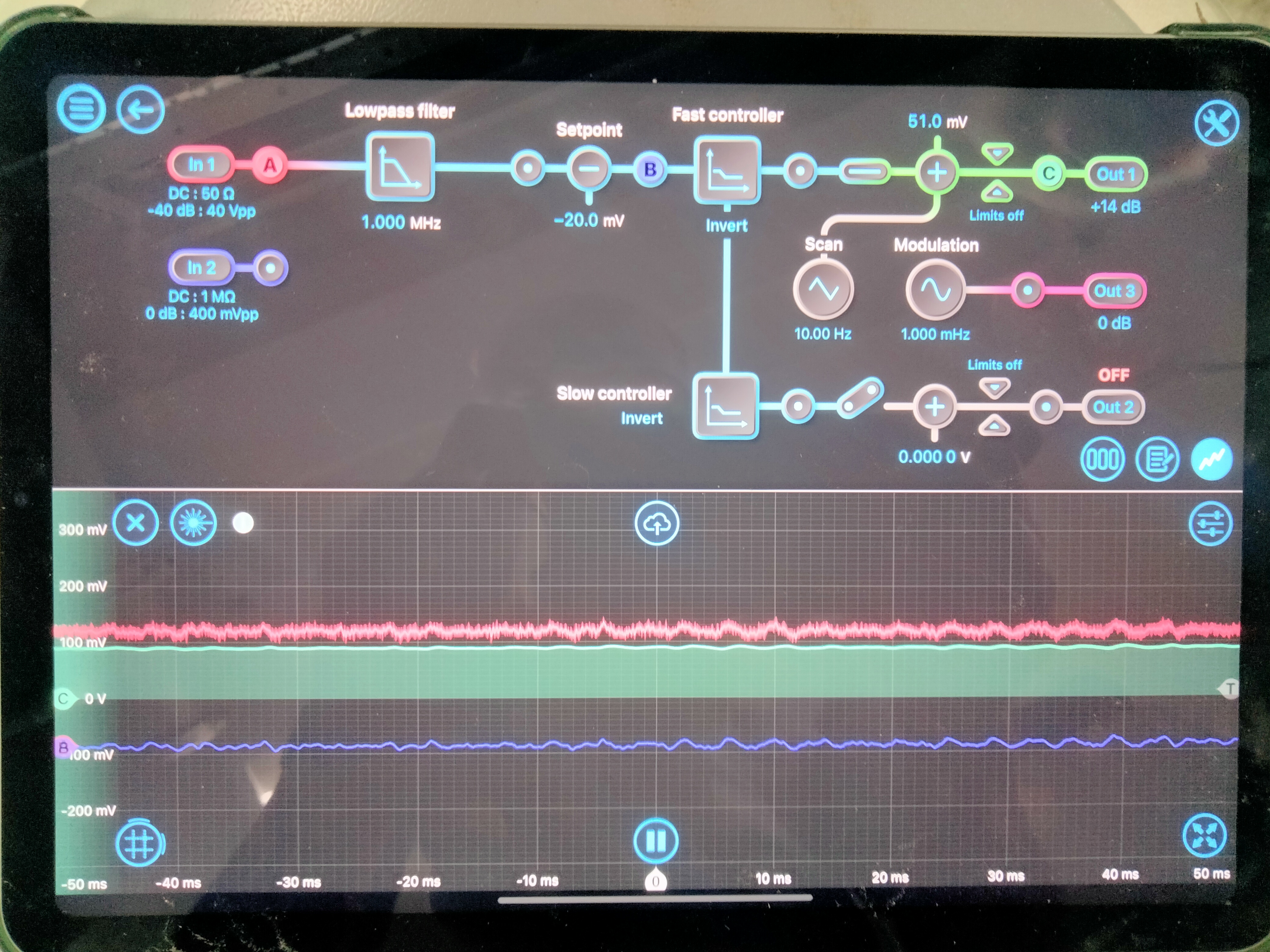
We sent a swept sine signal from the Moku to the piezo-mirror assembly (through the Thorlabs piezo controller). The actuated mirror is an end mirror of a Michelson interferometer, and we read out the response from the signal of a photodiode at the Michelson output. We used the Moku:Pro in multi-instrument mode, with the following instruments (see screenshot):
Slot 2: Laser Lockbox to perform a fringe lock.
Slot 3: Frequency Response Analyser to send a swept sine, record the response, and compute the transfer function.
Slot 4: PID controller to add the control signal and swept sine signal into one output signal.
We performed the transfer function measurement in two configurations:
I) Without feedback control of the Michelson fringe operating point (loop OPEN)
For this we first put the Michelson at roughly mid-fringe, then disabled the laser lockbox digital output and opened the loop. The transfer function is computed for the ratio of the Moku output signal (containing only the swept sine) and Moku input signal (containing the PD signal). See attached screenshot.
II) With feedback control of the Michelson operating point (loop CLOSED)
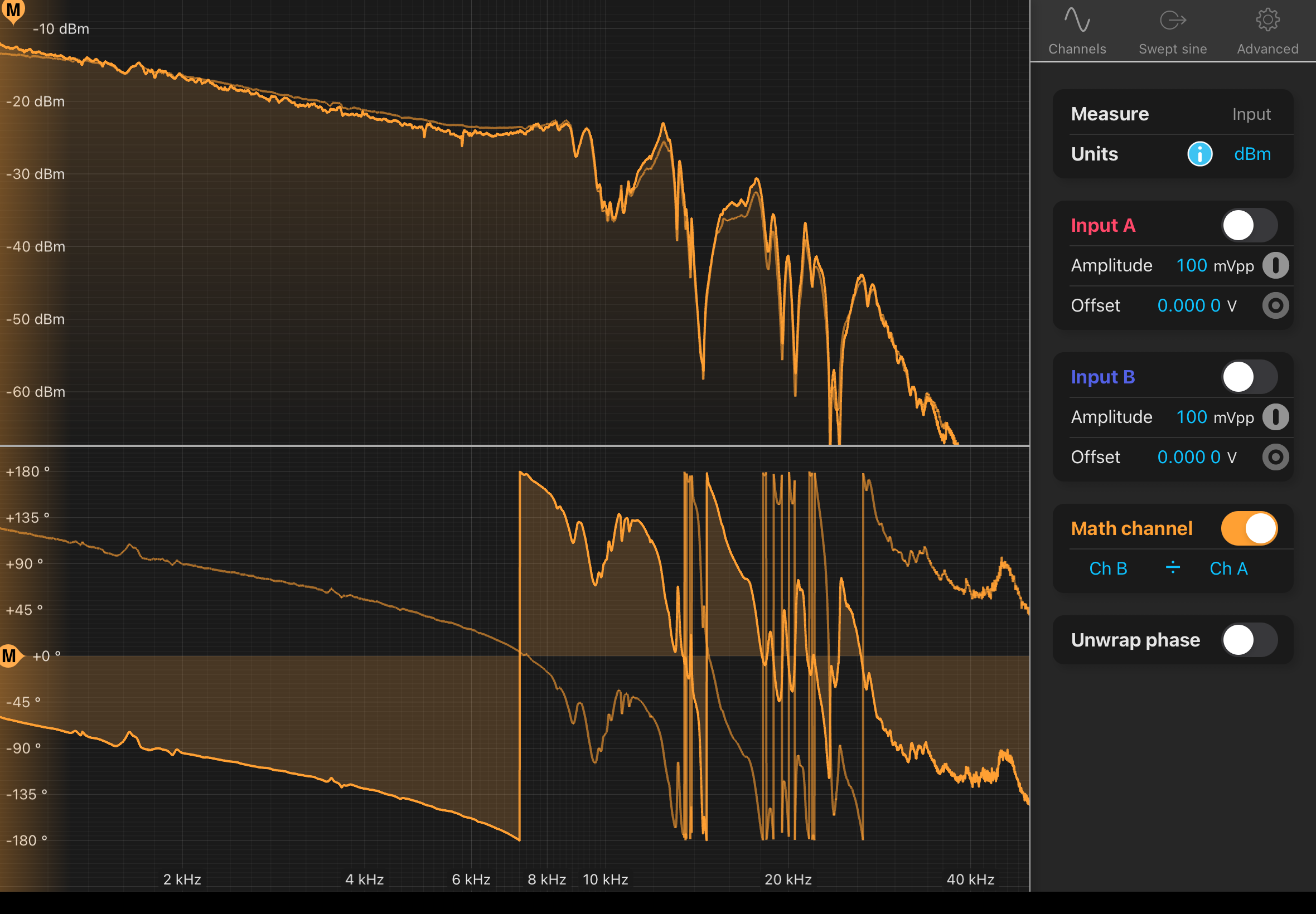
For this the control loop is closed and the Michelson is maintained at the mid-fringe. The transfer function is computed for the ratio of the Moku output signal (containing the swept sine and the control signal) and Moku input signal (containing the PD signal). See attached screenshot.
Both measured transfer functions appear very similar, as they should in theory. It appears the piezo-mirror assembly goes through resonance at roughly 8.7 kHz, although the fundamental peak is low-Q and hardly visible.

[Sander,Daniel,Ian,Torrey]
We moved the sled with the filter cavity to the cleaner table (table directly to the left when entering the room) and installed 3 newport 1550 laser line mirrors at each point on the filter cavity except for the input. We used the whole punched IR card to allow the input beam to enter and aligned the reflection of the 3 mirrors, i.e. one round trip in the cavity, to match the input beam. The beam incident on the cavity is now from the path of the power distrubution center previously used for Daniel's crusher tests.