Displaying reports 521-540 of 1095.Go to page Start 23 24 25 26 27 28 29 30 31 End
Reports until 17:51, Tuesday 30 July 2024
Atoms General
Briana Chen - posted 17:51, Tuesday 30 July 2024 (11791)
Locking!!!

[Briana, Ian, Torrey]

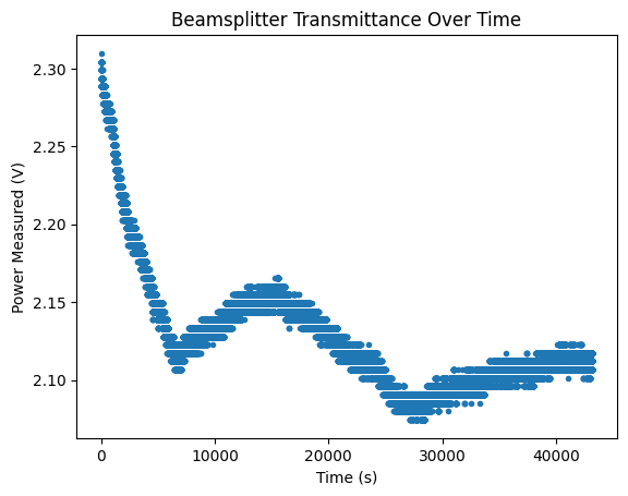
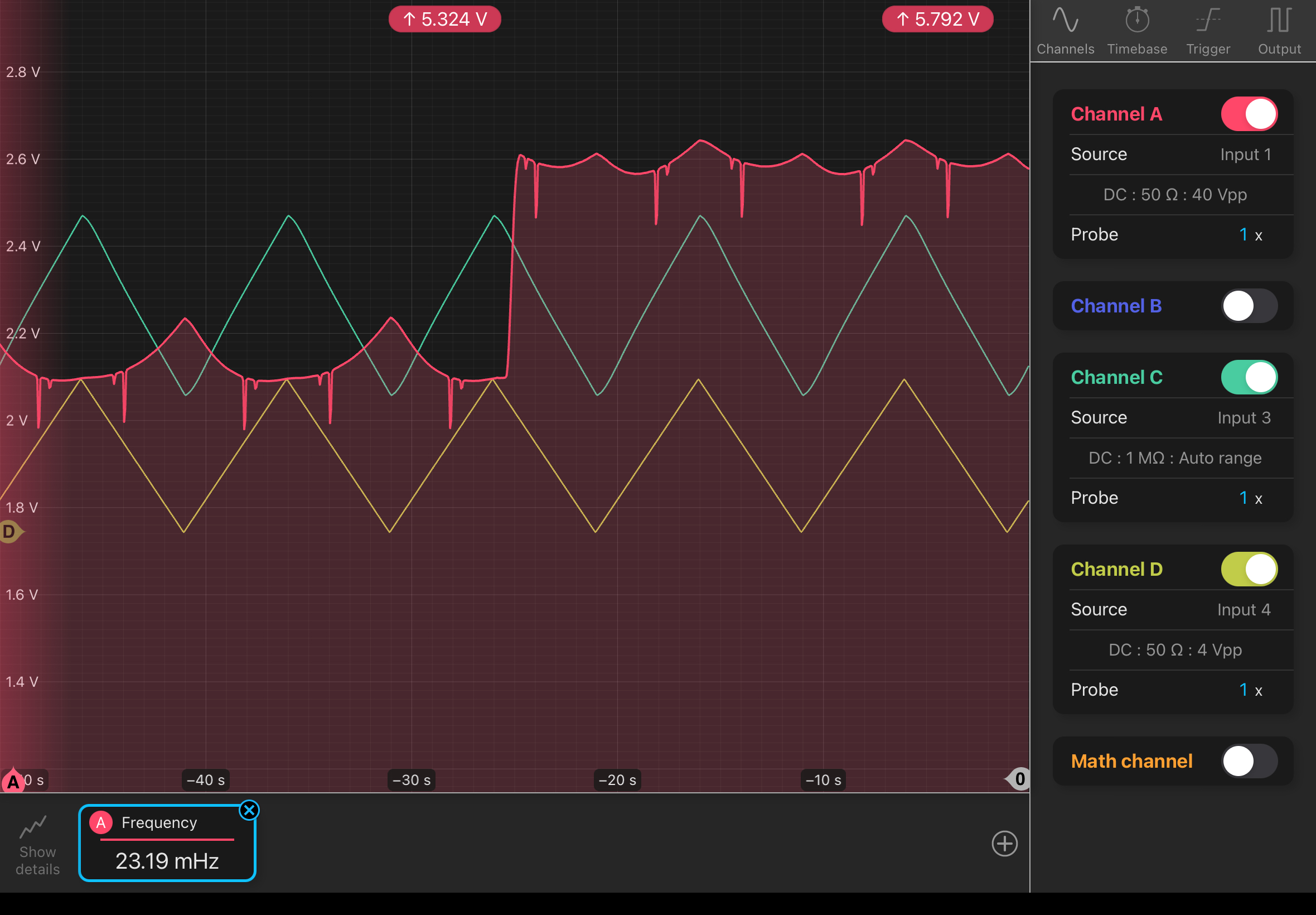
Before exciting stuff: This morning, I noticed that photodetector saturation was occurring at 3.3 mW. All settings were the same as yesterday (Input 1 channel at 50 Ohms, 40 Vpp). The way that I returned to yesterday's voltage level was to switch to 1 MOhm and then switch back to 50 Ohm. For some reason, this gets you back to the higher voltage level. You also have to be at a high-enough power (>5 mW I want to say? Certainly 8 mW) for the lack of change between 1 MOhm and 50 Ohms to occur. I have no idea why- the change from 1 MOhm to 50 Ohm should change the voltage reading by a factor of 1/2. Either way, this process returned it to the voltage level from yesterday (~6 V). 

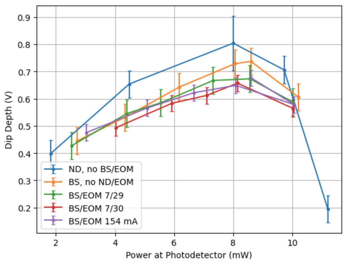
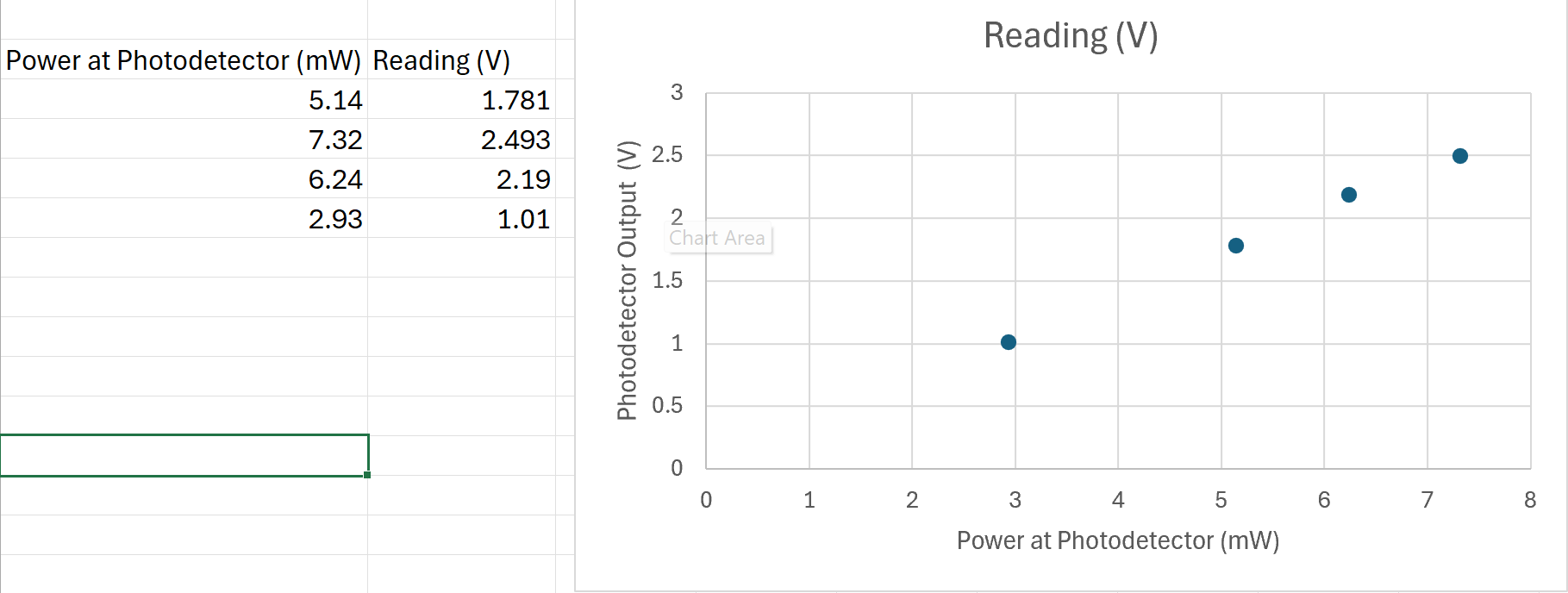
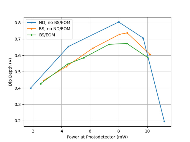
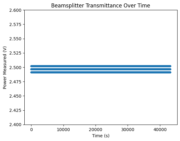
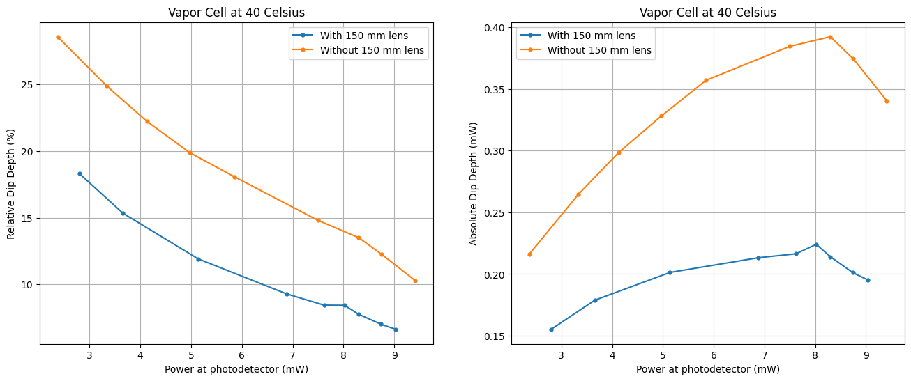
Retook some dip depth measurements to check repeatability- it seems repeatable within the error bars (power error bars are too small to be seen): dips.png (red and purple lines were taken today). Even at a different current, the saturation tends to occur around the same place. This is plotting absolute dip depth, which will help us determine at what power saturation occurs. Data is here: 7_26.xlsx

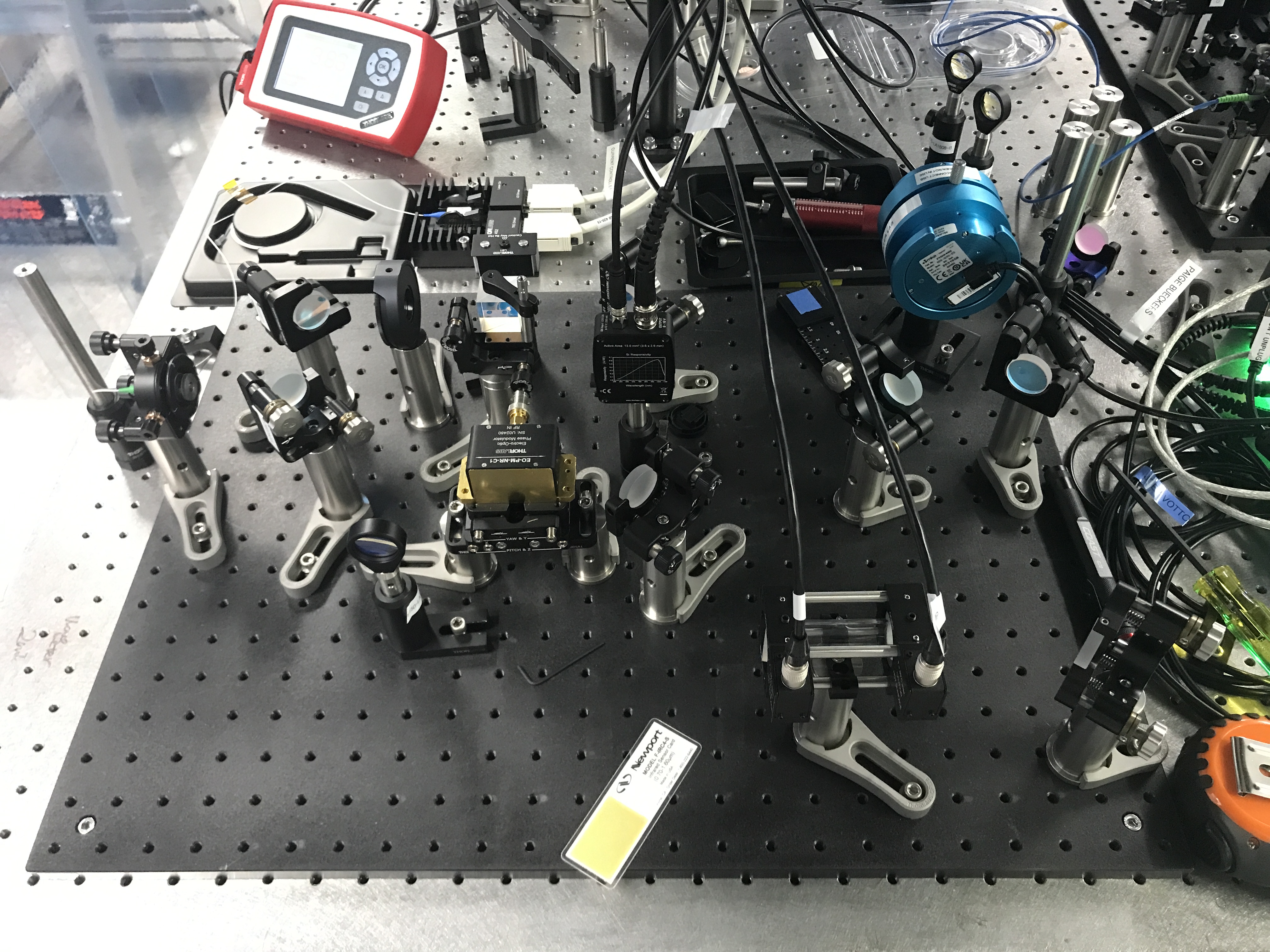
Shoutout to Torrey for figuring out that we need a high-bandwidth photodetector to detect the higher frequency signals, so we needed a PDA10A2 detector (150 MHz) instead of the PDA36A2 detector (12 MHz). We exchanged our 36A2 with Torrey's 10A2. The 10A2 has an active area of about 0.8 mm^2 (1 mm diameter ish), so we may need to add a lens to focus it down. We also added two ND filters (a 2 OD and 0.3 OD filter) so that only ~0.166 mW hits the detector. Both filters should be placed right before the photodetector so the light going through the vapor cell is still a high power. Will call Thorlabs to ask what the damage threshold is, but Torrey remembers it being around 1 mW, which is why we added the ND filters. 

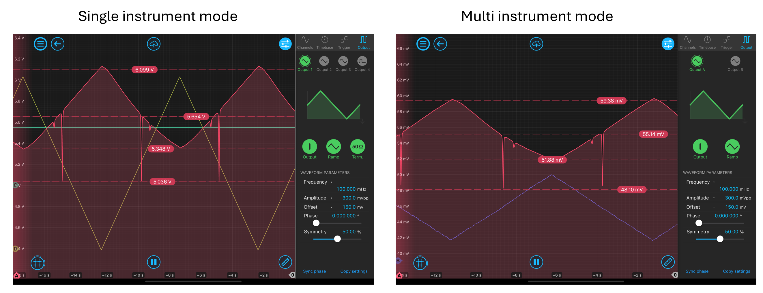
The confusion with the attenuation of -40 dB automatically by the multi-instrument mode means that the signal in single instrument mode should be multiplied by 0.01 (-40 dB = 10 log (P2/P1) = 10 log (V2^2 / V1^2) so V2 = 0.01 * V1). This is approximately the case: mimvssim.png. There doesn't seem to be a way to change this, it may just be the way the MIM operates. It is probably fine too since we have a low power hitting the photodetector now anyways. 
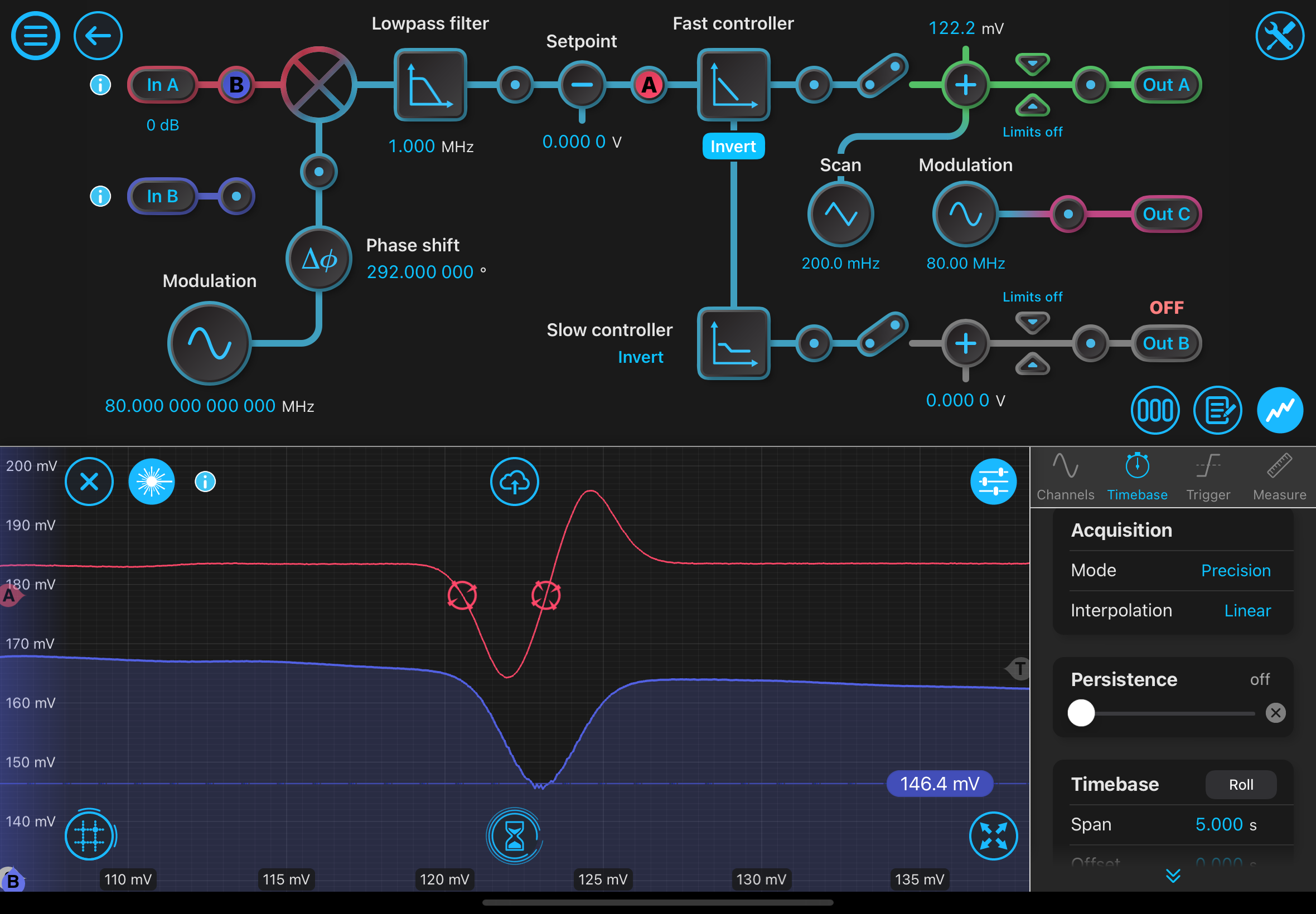
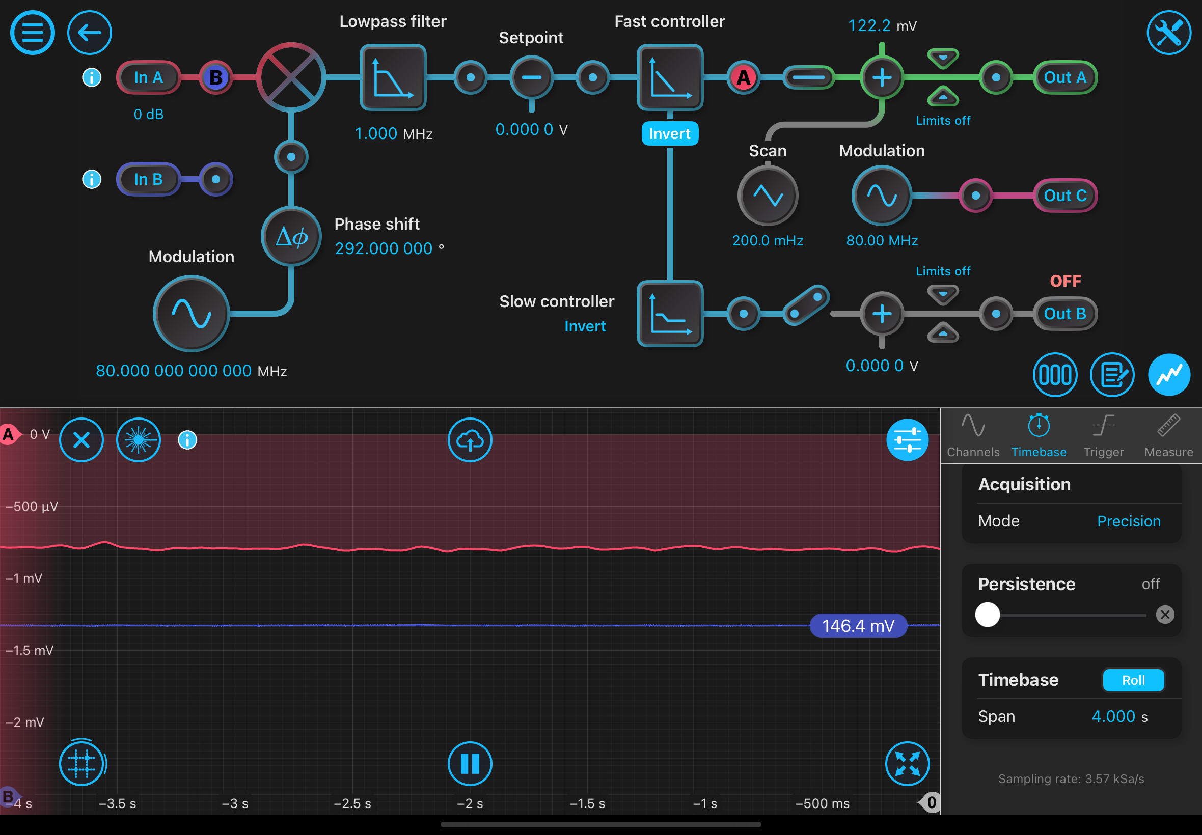
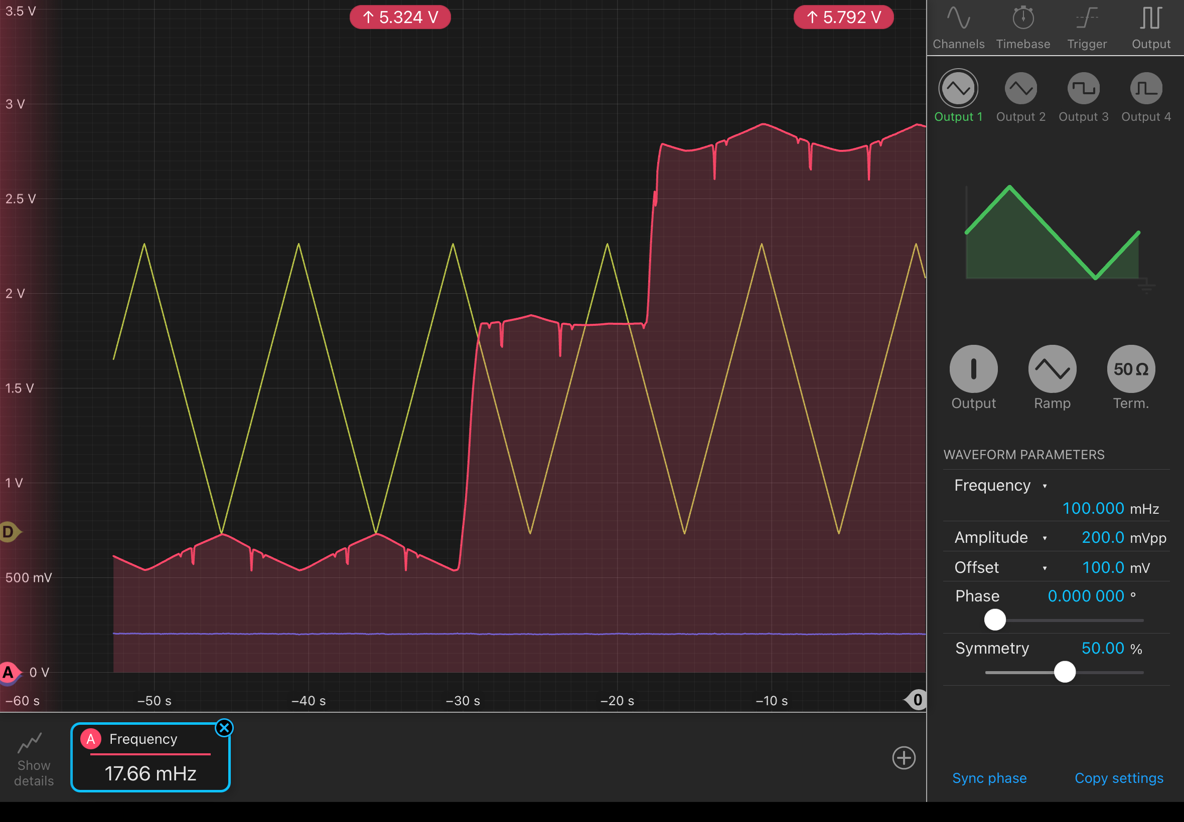
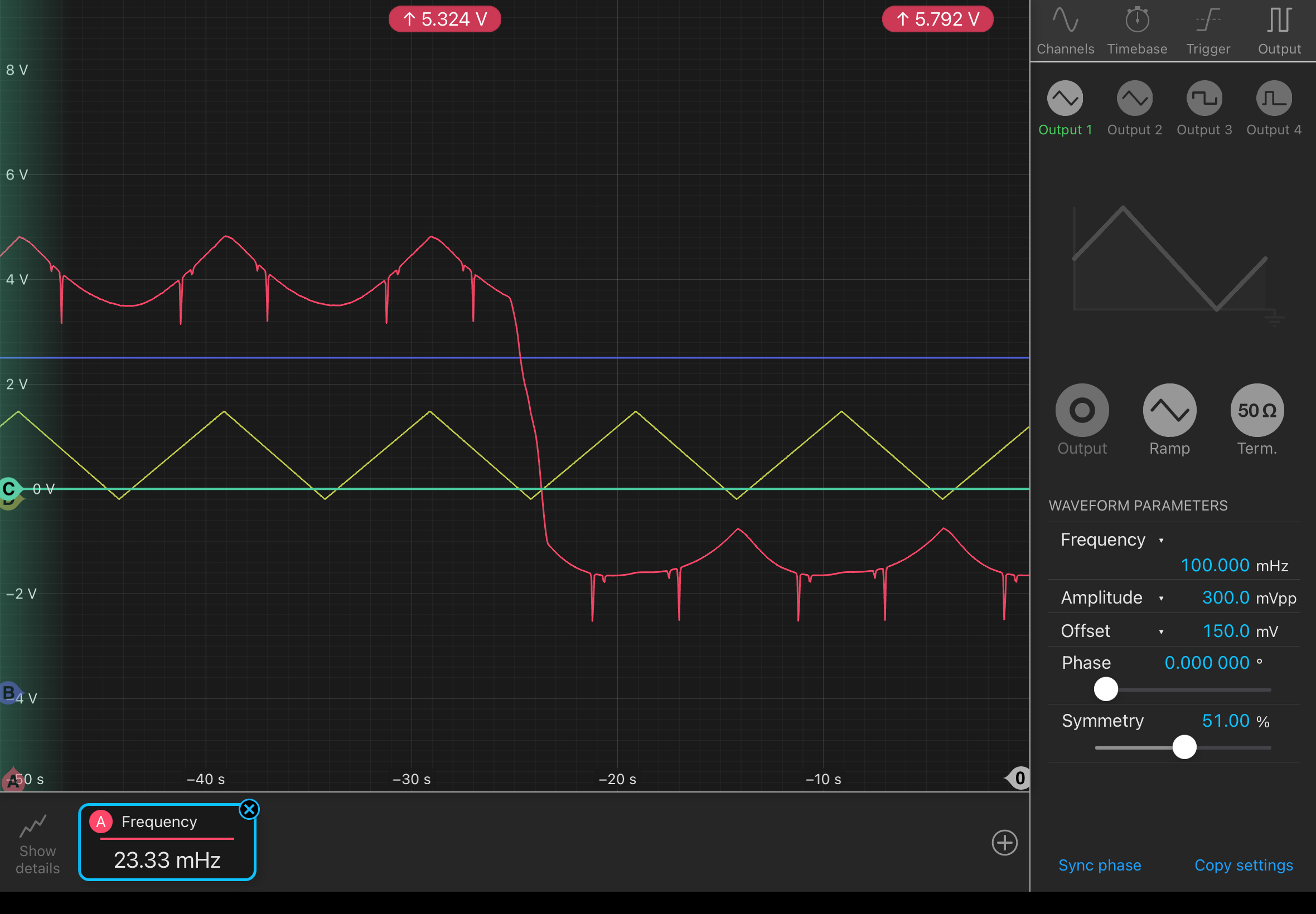
Locking!:

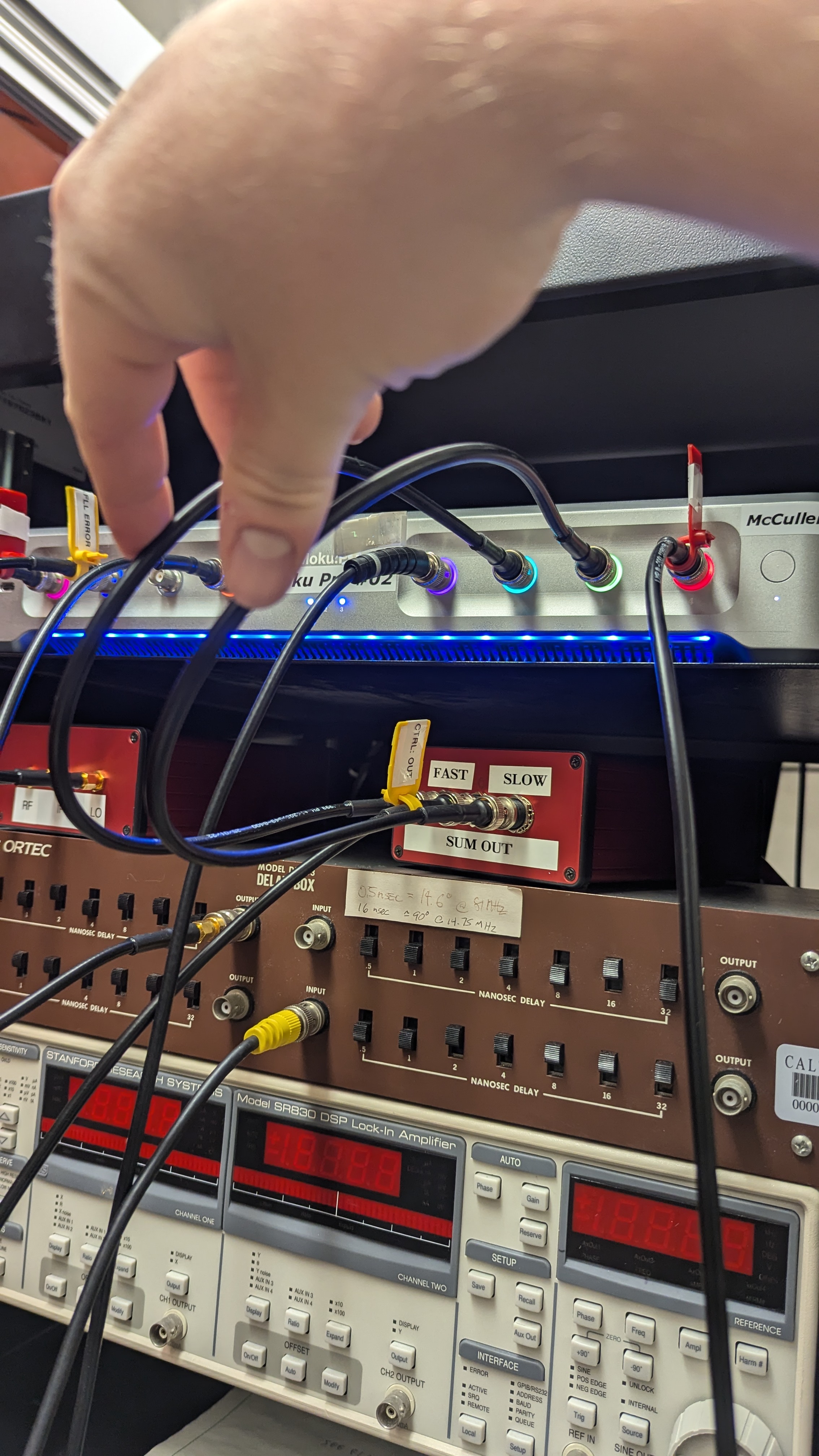
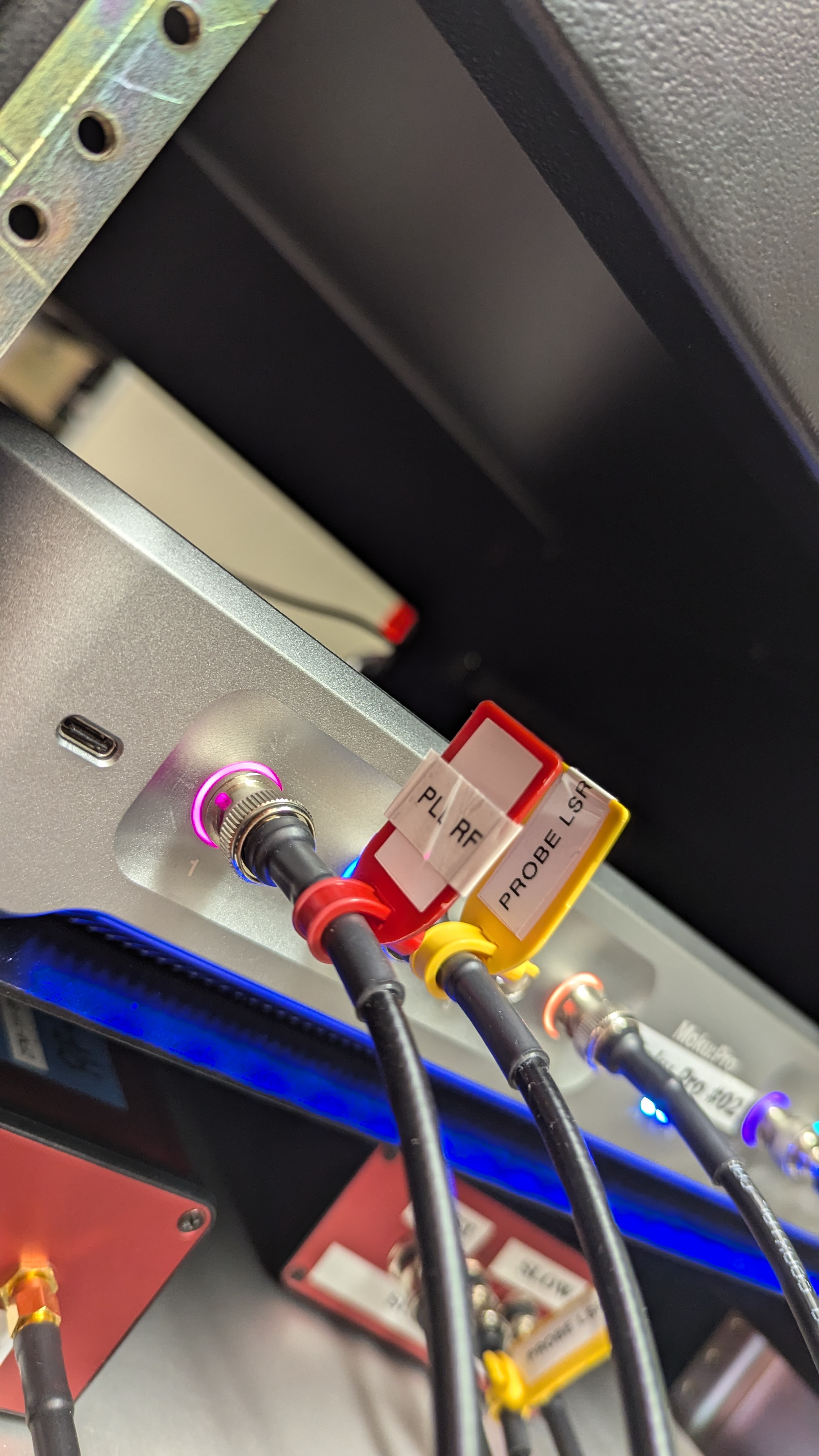
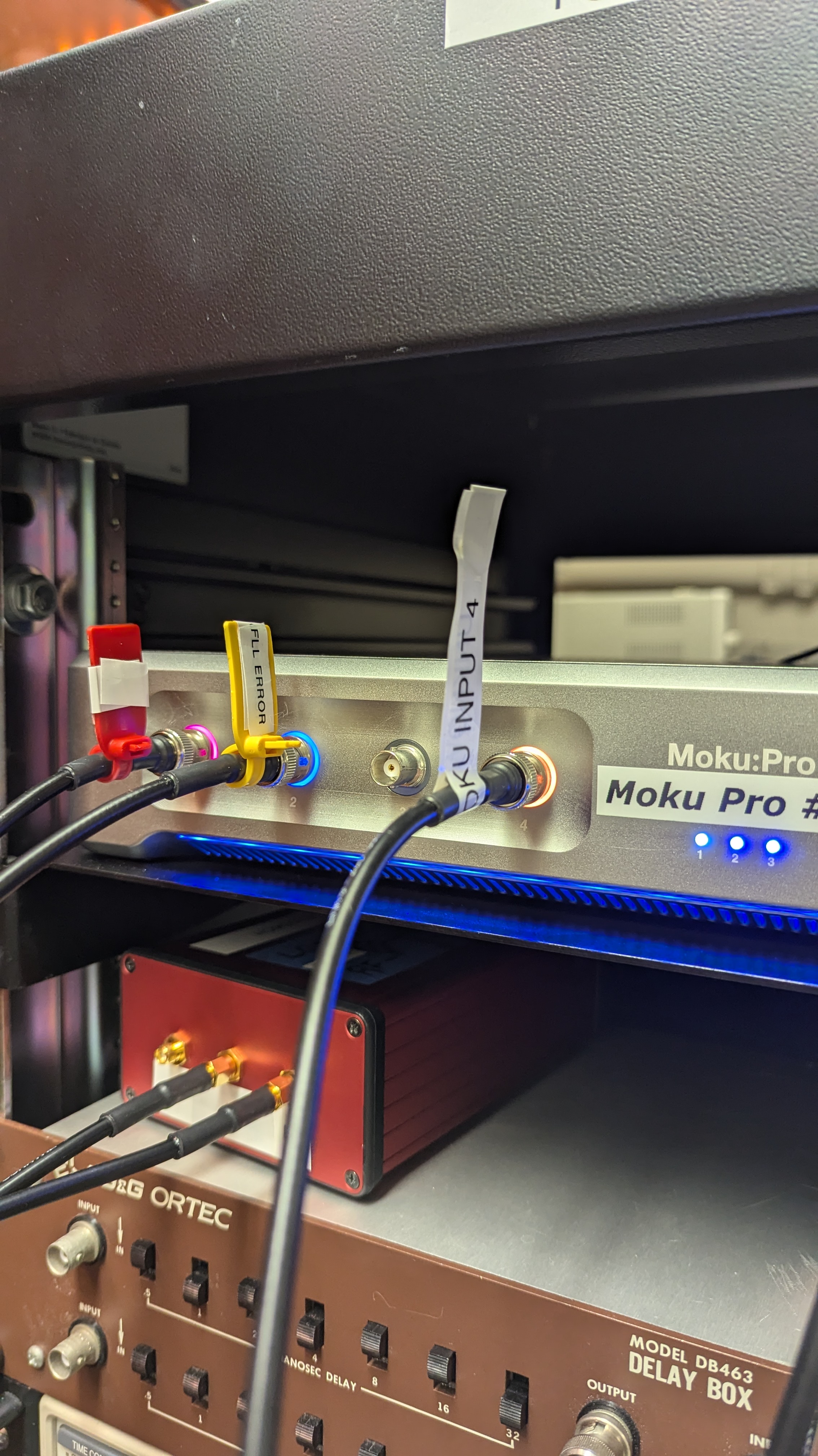
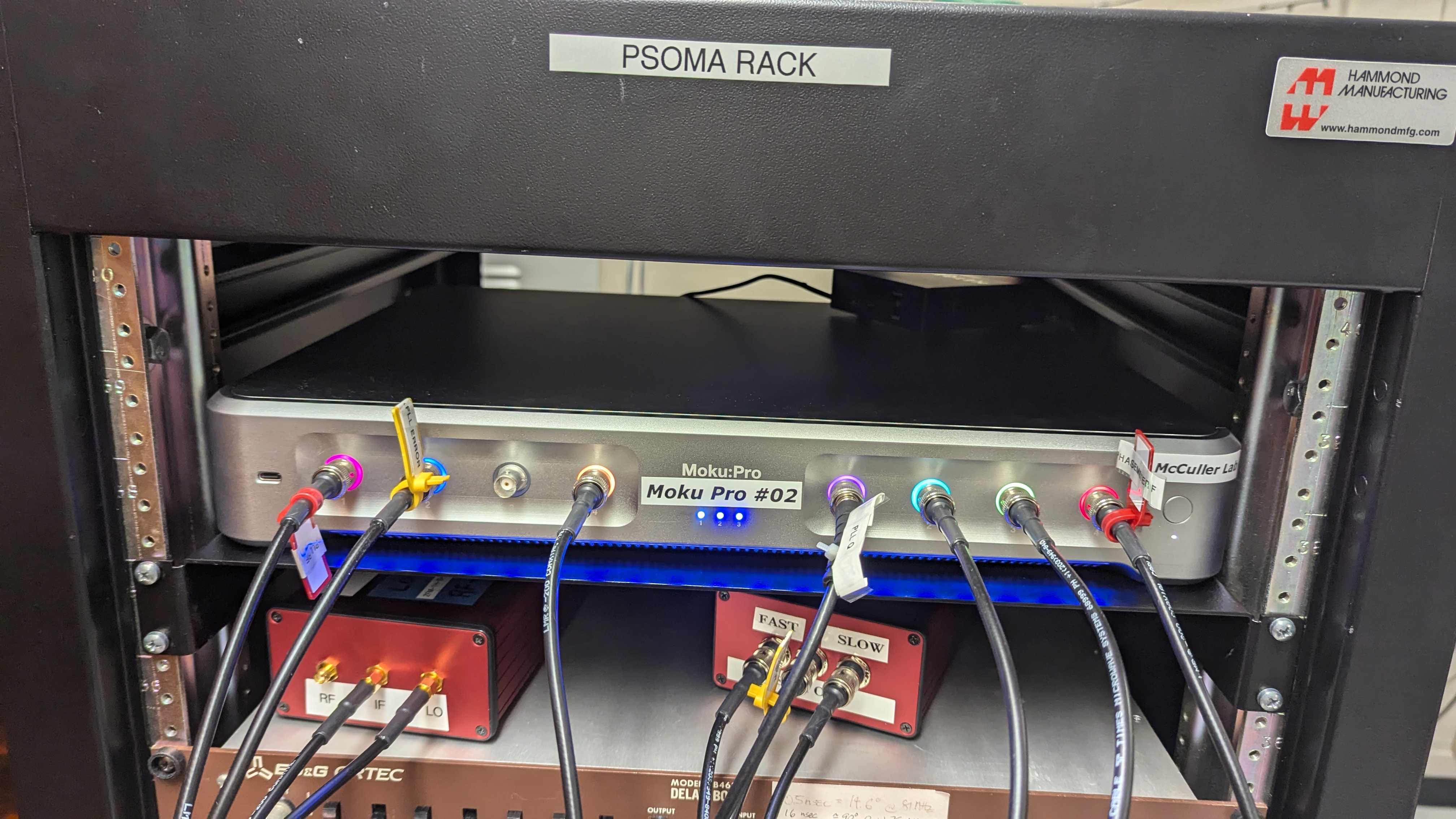
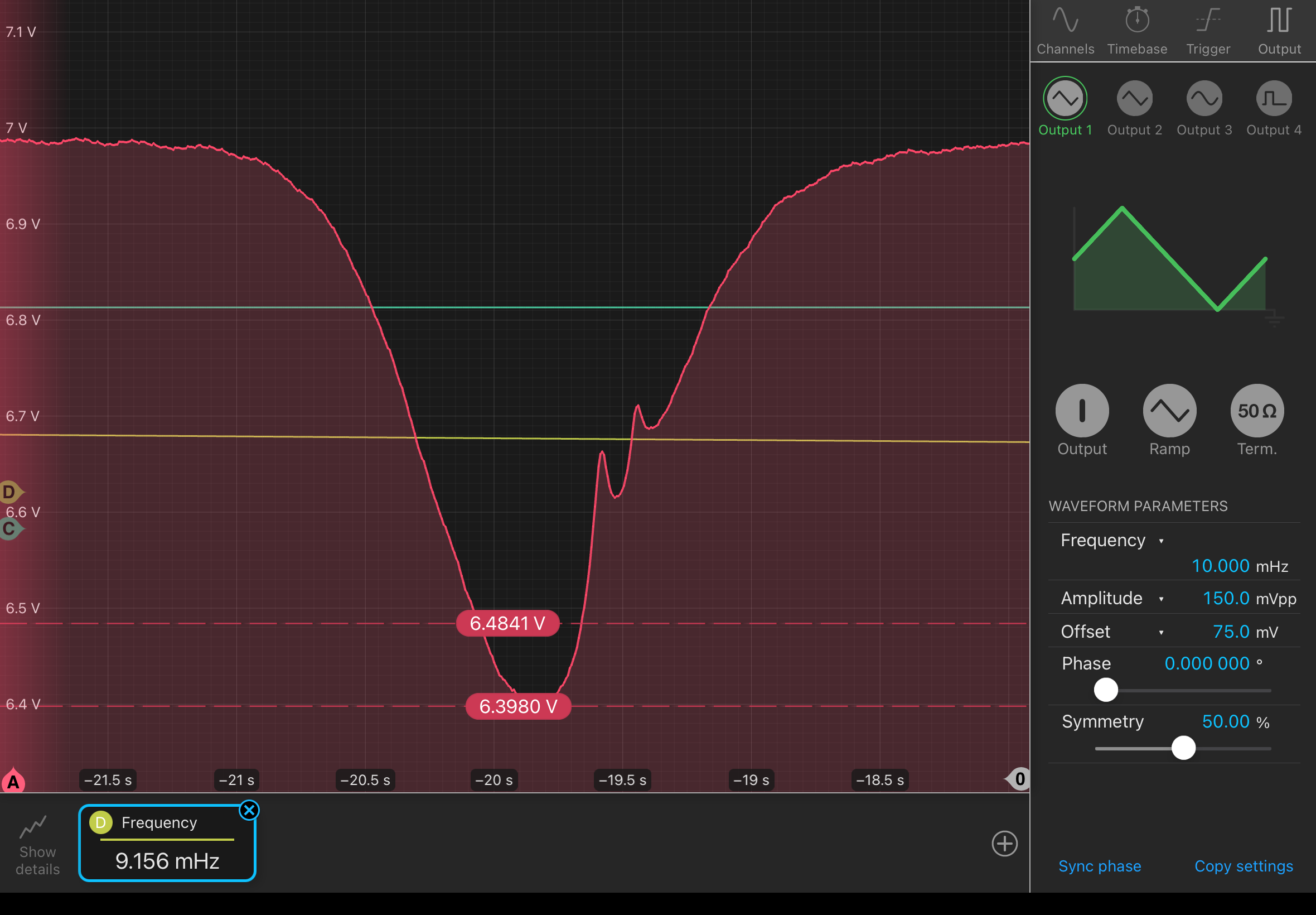
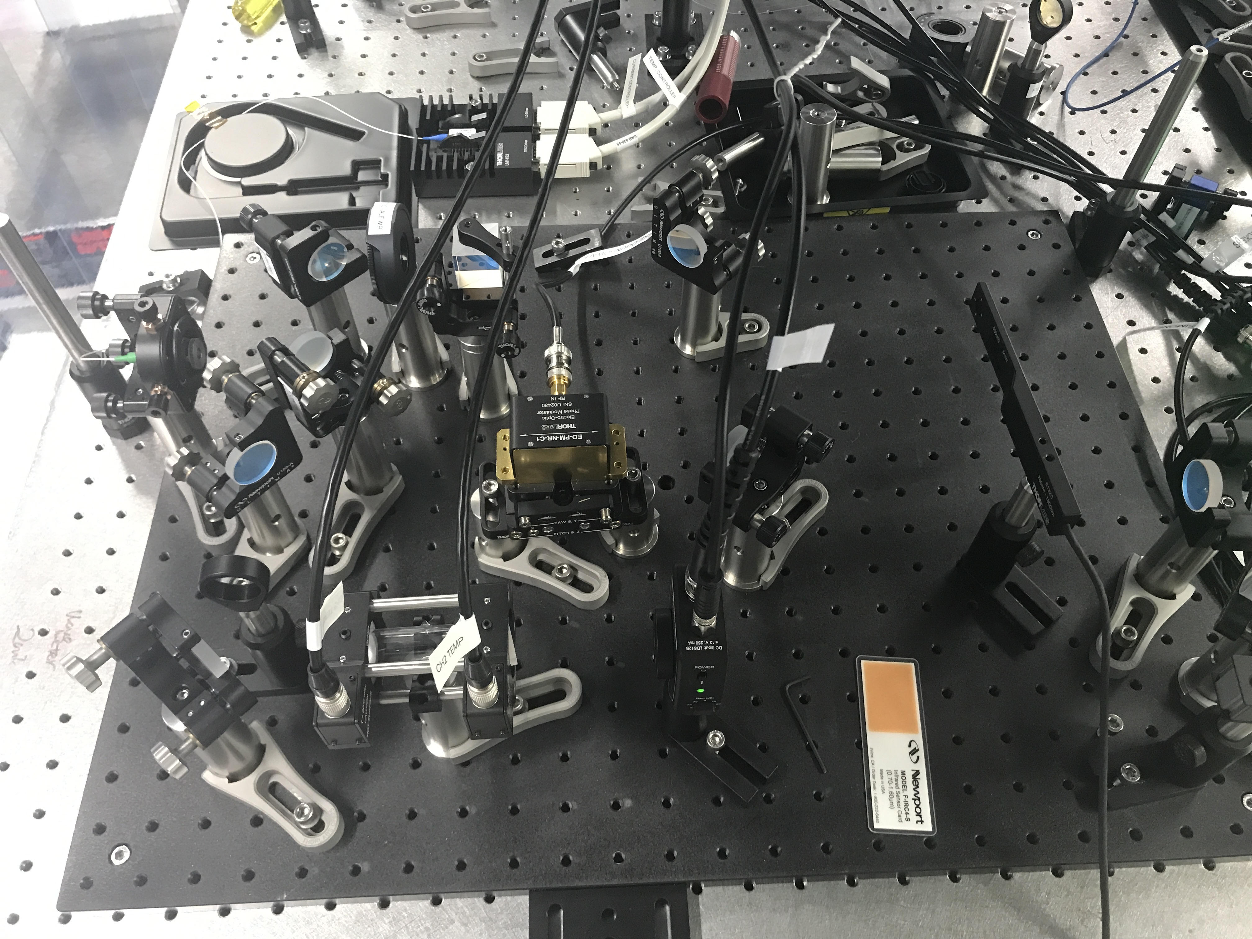
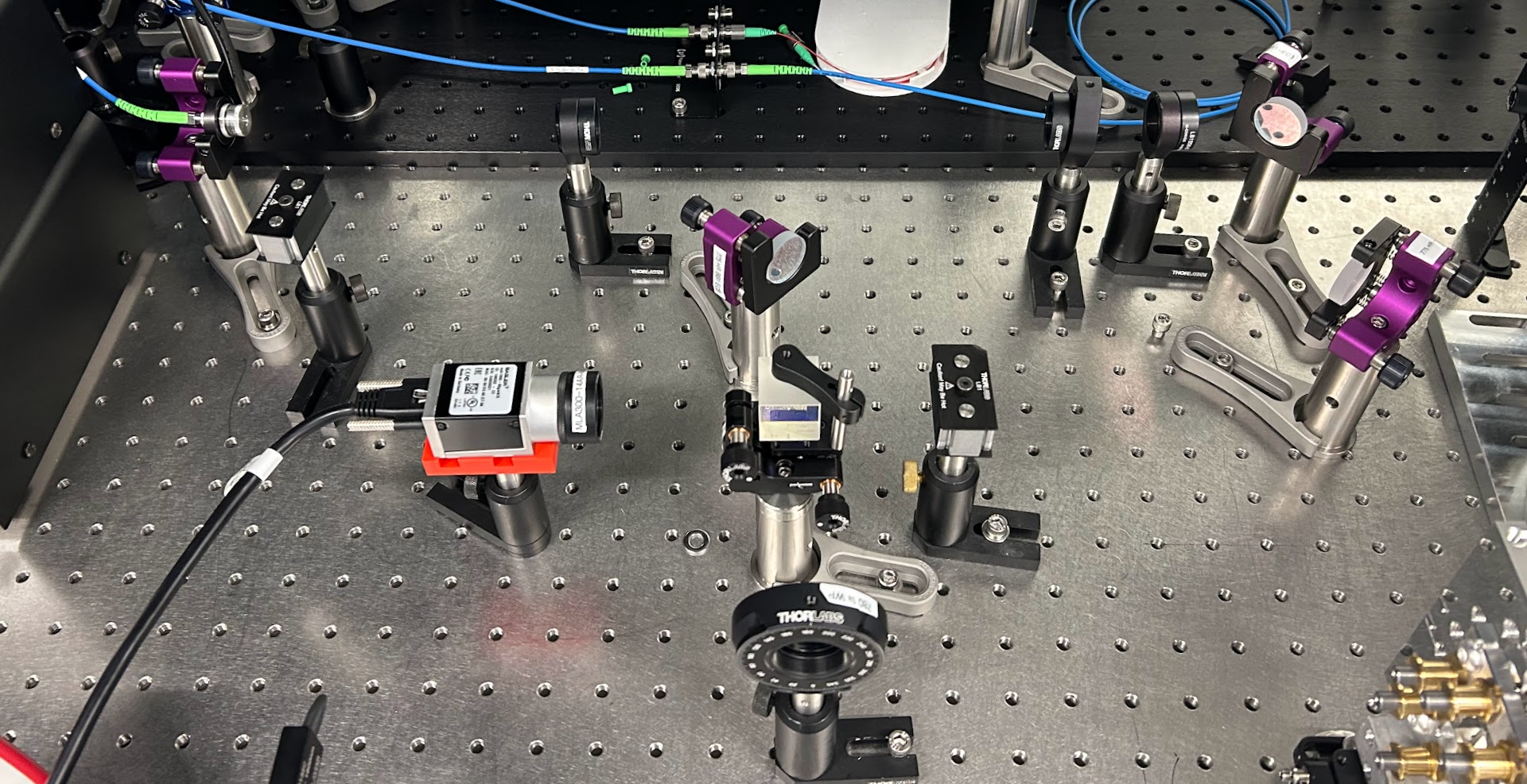
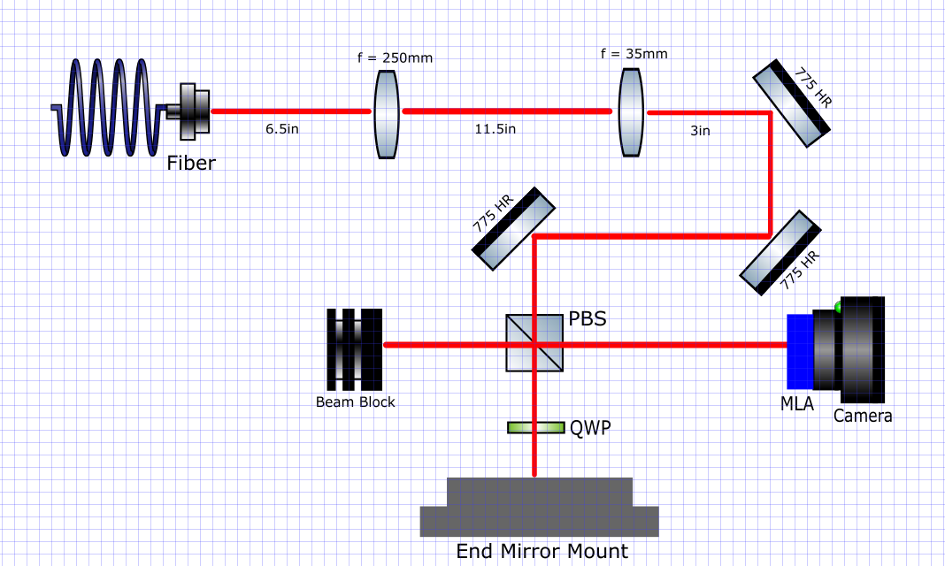
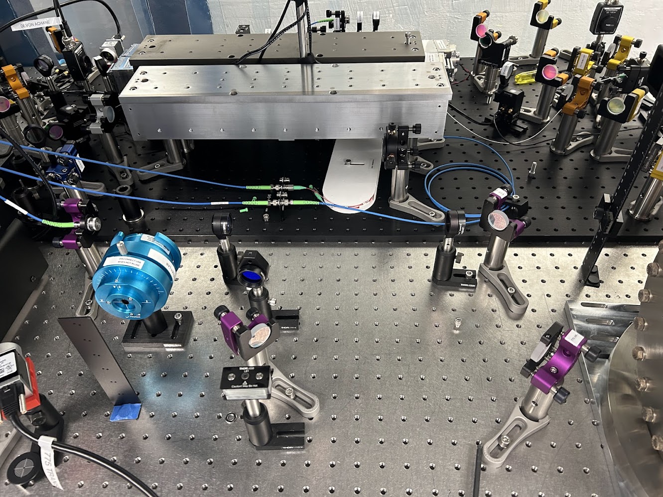
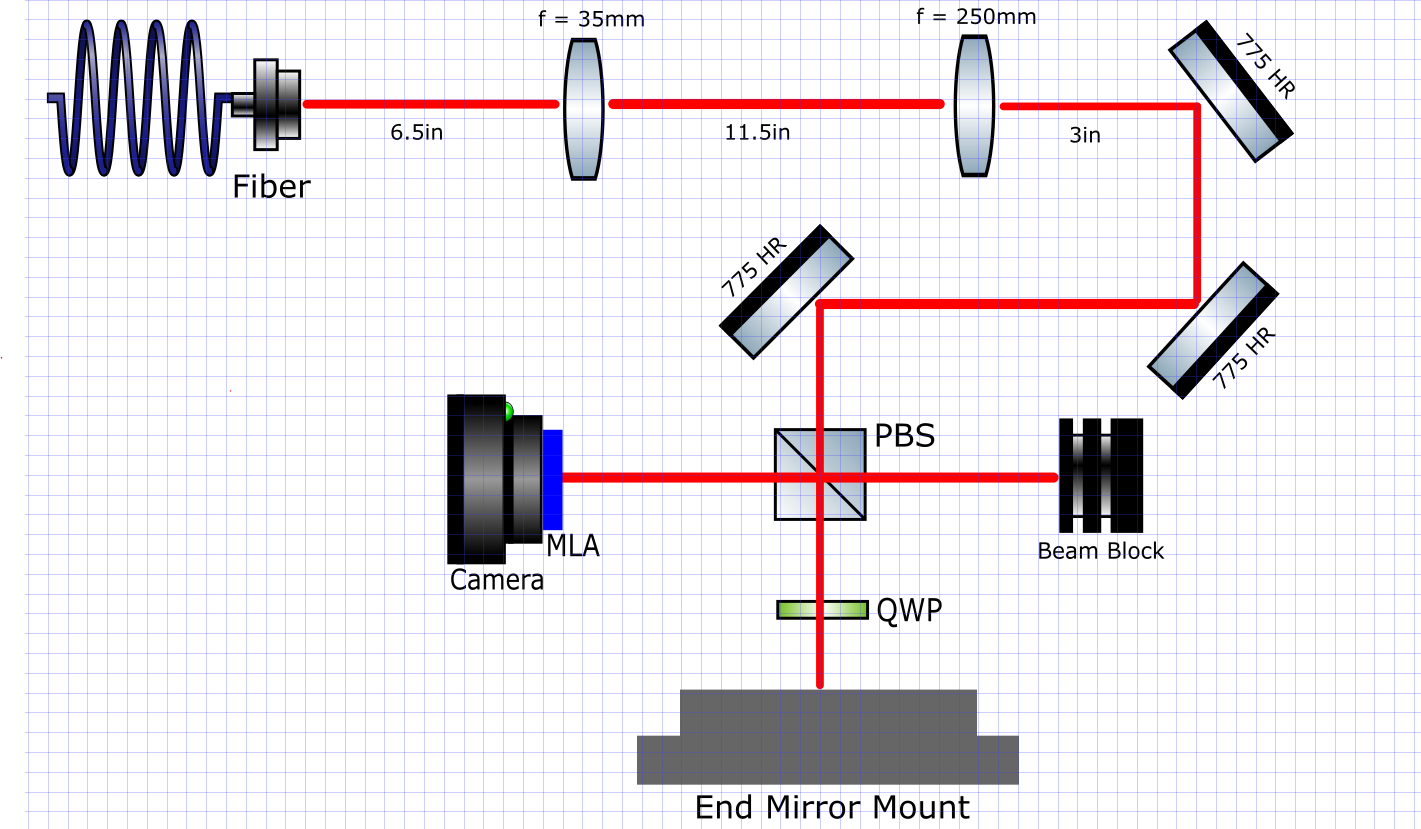
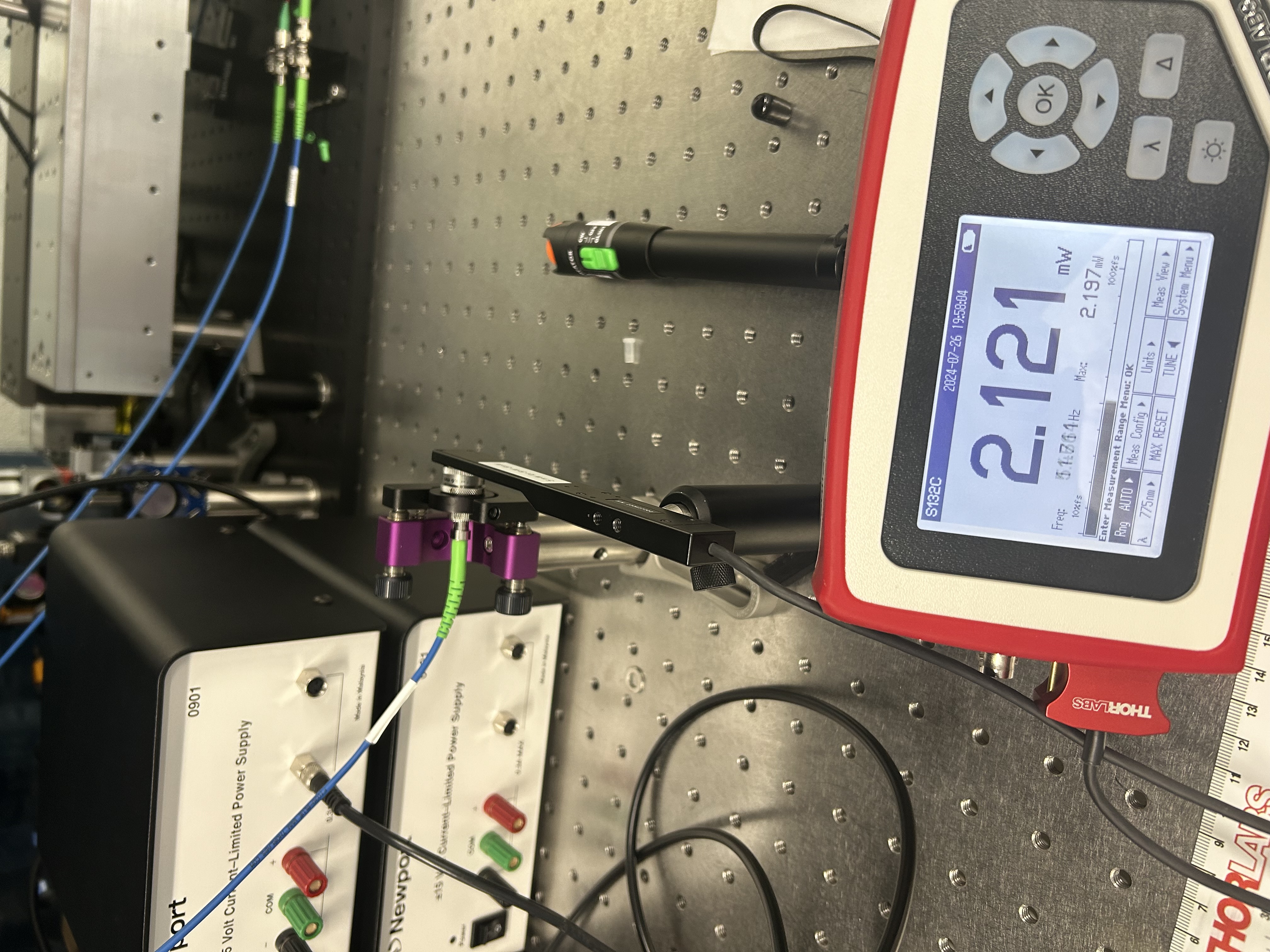
We locked the laser to the main absorption dip!! See pictures of the error signal (errorsignal.png) and the result when locked (locked.png). It seems like the controller should operate at lower frequencies (15 Hz) to best lock, which Torrey pointed out is different from the kHz frequencies he is using for the cavity locks and means we could consider using the slow controller. Torrey definitely did not lock the laser or help at all. The next step is to better understand the locking process before Ian deletes it all. Also, should tune controllers/modulation frequency/phase to make sure the error signal is maximized. Setup is same as in the picture last post except now with a different photodetector and some ND filters. 

Images attached to this report
Non-image files attached to this report
GQuEST SHG (GQuEST)
Daniel Grass - posted 16:47, Tuesday 30 July 2024 (11795)
AOM path for OFC 3 starting to be built

[Torrey, Daniel]

I placed a 150 mm focal length lens after the PBS on the 3rd SHG path and setup the AOM on the 5 axis mount. I logged the AOM here and labeled it.

We will need a way of powering the AOM. I think we need more 2 W supplies. We also need irises. I am working on getting more irises.

GQuEST Output Filter Cavities
Torrey Cullen - posted 16:33, Tuesday 30 July 2024 (11794)
Filter cavity two lock acquired

Aligned a REFL PD, transferred EOM and laser current control to the newly (re)acquired moku (2), and acquired lock in the new filter cavity. Want to do some ringdown measurements on the new cavity tomorrow and see how the finesse compares.

Images attached to this report
Equipment Loans
Torrey Cullen - posted 11:02, Tuesday 30 July 2024 (11792)
Moku returned from Cryo Lab

I've taken our moku back that was on loan to the cryo lab. It is now underneath Moku 1 in B102. Below is documentation of the cables I had to unplug in the cryo lab in order to remove it from the lab.

-Initial State

-Left side labels & left side labels 2 - Note: input 4 was unlabeled and twisting deep into a spot with many BNC cables. I have labeled it "Unknown Moku Input 4" as seen in the photo.

-Right side labels & right side labels 2 - Note: 2 outputs are unlabeled but you can clearly see where they are originating.

-Back Side Labels & Back Side Labels 2 - Note: Both the ethernet and BNC on the backside were unlabeled. I have added labels "Moku Ethernet" and "Clock Ref In".

This will be duplicated on the ELog here

Images attached to this report
Atoms General
Briana Chen - posted 23:42, Monday 29 July 2024 (11787)
Saturation issue resolved (kind of) and dip depth measurements with EOM/beamsplitter

[Briana, Ian]

The varying levels at which the photodetector saturated was a concern. For example, in the 7/25 data, the photodetector was saturating around 3.3 V. Earlier today, 9.4 mW at the photodetector (current controller at 145 mA) saturated the detector, which was a setting that we were able to achieve without issue on 7/25. The photodetector response could even reach 7V in some previous data. I measured the power incident on the photodetector and the outut reading to confirm that the photodetector reading is linear as expected from specs, which it seems to be (linearphotodetectorresponse.png). The solution for this issue was to set the Vpp on the channel of the photodetector to 40 Vpp so that it could reach a higher voltage- it was cutting off at 2.5 V because the setting was only at 4 Vpp. 

This still does not explain a few things to me. First, the photodetector reading should only read 0-5 Volts for a 50 Ohm impedance, which is what the BNC cable provides. In our measurements today, we could achieve >5V without saturation. There were no setting that I am aware of that were set to add gain/amplification. Also, the PDA output has a 50 Ohm series resistor and this alongside the output impedance produces a scale factor that is proportional and determines the output (in Volts) from the photodetector. The scale factor is R_load / (R_load + R_series) so if the Moku is providing a 50 Ohm impedance versus a 1 MOhm impedance, the output voltage should be different by a scale factor of around 2. This is not the case also when we change the Moku settings from 50 Ohms to 1 MOhm. However, with this 40 Vpp setting, we get bigger dips (around 0.7 V at max) than before because obviously the signal is not getting limited by the 4 Vpp setting, so maybe it is fine?? Not sure what I'm missing with how the photodiode works. 

Either way, if only a flat line is seen from the photodetector, it is probably saturating. This is also probably the case for why the multi-instrument mode (MIM) oscilliscope was different from single instrument oscilloscope- MIM seemingly only allows 400 mVpp and any attempt to set it to 4 Vpp is accompanied by automatic attenuation. Not sure how to fix this setting yet. 

I took dip depth measurements again today to start repeatability confirmations, which I will test tomorrow. I first removed all the beamsplitter/EOM stuff and took a dip depth measurement using ND filters to vary power. Then, I put the beamsplitter in and measured. Finally, I aligned with the beamsplitter and EOM. The measurements of dip depth are compared here: dips.png. The dip depth measurements (done roughly using the voltage lines on the oscilloscope) seem to agree with the saturation point from previous data (7/25). It seems that as the light passes through the beamsplitter/EOM, there is a decrease in dip depth. This does not have to do with losses since the x-axis of these plots is the amount of light hitting the photodetector. This could be, as Ian suggested, because the vapor cell somehow responds differently to a certain polarization of light (currently p-polarized light passes through the vapor cell). I can try these dip measurements again with s-polarized light instead to see if it responds differently. Note: the very last data point of the graphs with the beamsplitter and beamsplitter/EOM (highest power) was taken at a current of 154 mA to get to the necessary power (because of losses through the EOM/beamsplitter). The maximum power that the beamsplitter could achieve was the power at the second to last data point. It would be good to take data also at a higher operating current, which could also answer the question if the dip depth saturates at the same power for different currents. Because the polarization still drifts, some of the temperature scans are weirdly inverted. Not shown error bars: uncertainty in power at photodetector is estimated to be around 0.05 mW, uncertainty in dip depth around 0.05 V. See data here: 7_26.xlsx.

Also, you can see the small dips! Again, not sure what enables the resolution to capture these (alignment? right orientation/power through the vapor cell?) but it's nice to see them: c142_p6_main_20240729_181728_Screenshot.png. Will fit line profiles to them to see what the differences in wavelength are (corresponding to what transitions). 

There may be additional losses from the EOM if the output from the laser changes in polarization (drift) since the efficiency through the EOM is determined by the polarization. We are going to try turning the laser tomorrow. Current setup: IMG_2374.jpg.

Labelled inputs/outputs to Moku as follows:

Input 1: Photodetector measurement (labelled Caitlin Clark). 

Input 2: input to EOM, coming from Output 3 (labelled Simone Biles). 

Input 3: CTL OUT (labelled Paige Bueckers). 

Input 4: TUNE IN (labelled Joey Votto), coming from Output 1.

Output 1: temperature control (labelled Joey Votto). 

Output 3: input to EOM (labelled Arike Ogunbowale). Output 2/4: none

Images attached to this report
Non-image files attached to this report
GQuEST End Mirror Mount (GQuEST)
Erin McGee - posted 21:31, Monday 29 July 2024 (11790)
Shack-Hartman Wavefront Sensor Setup + End Mirror Mount Assembly Complete

[Erin, Daniel]

We first wanted to find a way to change the polarization of the light in the Shack-Hartman Wavefront Sensor setup so that all of the light going through beam splitter is transmitted. We could do this by rotating the fiber itself (carefully, without straining the fiber). This had a tendency to misalign the lenses and the mirrors when done without changing the setup however, so a much better strategy is to move the beamsplitter so it is right after the fiber collimator, and then rotating the fiber until the beam fully transmits (using the power meter to make sure). Then the beamsplitter can be returned, and any final alignment can be done.

After that, we aligned the quarter wave plate, and added a 775 HR mirror where the end mirror mount would go, just for testing. We also made sure the polarization angle maximized the light output back out of the beamsplitter (see the setup). 

Then we set up the MLA and attached it to the camera using an adapter. We got some really interesting images (see attached) and ended up adding an ND filter to both protect the MLA/camera from a strong beam and to make the images a bit sharper. I took several different images of the 775nm HR mirror at different distances, with different ND filters, and added a lens 300 nm lens after the mirror create the effect of a curved mirror. I am going to use an adaptive optics python library I found and see if the SHWS analysis feature works (if not, there is are a few MATLAB ones that should also work). If neither of these are good, I also took an image without the MLA so I can compare the two to determine how much the array moves the light. I also want to see if it is necessary to image the entire set of all 300 mircolenses, or if only a region is sufficent, and if the MLA needs to be rotated, or if I can just rotate the image. 

We also finished assembling the end mirror mount (see attached) and we added the parts that allow us to adjust the pressure on the mirror itself. I plan to start imaging the uncoated silicon mirror tomorrow as well using the MLA. 

I also made sure our setup collimates the beam using Ian's gaussian beam fit code and while the beam isn't exactly symmetric, the waists are extremely consistent across several different distances (see the attached graph). This is a good sign, since it means we can image a 6mm diameter center of the silicon mirror consistently.  

Images attached to this report
GQuEST Output Filter Cavities
Torrey Cullen - posted 17:59, Monday 29 July 2024 (11788)
OFC2 Aligned

[Ian,Torrey]

OF2 is aligned! Process is the same as described in the past. More difficult having the input coupler as the static piezo mirror this time. Attached is a cavity scan for both cavities. It seems that the new one is much better aligned, although we should double check on a faster TRANS PD.

We went to lock it and noticed that the tank circuit on the 775 EOM had a wire broken. We resoldered in a new metal box to prevent this in the future.

Tomorrow we will take back the fourth moku and outfit it to control the second filter cavity as well as align the 1550 test light.

Images attached to this report
GQuEST End Mirror Mount (GQuEST)
Erin McGee - posted 18:42, Sunday 28 July 2024 - last comment - 20:20, Monday 29 July 2024(11786)
Shack-Hartman Wavefront Sensor Setup

[Erin, Daniel, Torrey]

We first profiled the 775nm light coming from the fiber that we ran from the larger table. We found that it was a bit smaller than a waist than we were looking for (we want a 3mm beam waist to image as much of the mirror as possible), and decided to use a pair of lenses to diverge the beam and then to collimate it. We used JamMT to find a solution for this, which suggested a 35mm and a 250mm set of lenses. We aligned those and tried to re-profile the light, but we were finding that the radius of the beam was too large to use the beam profiler, and some was getting cut off. We switched to using the Basler Ace 775mm camera with an ND filter to cut down on some of the light and get a better image, and took 5 measurements, varying the camera at different lengths so we could tell if the light is collimated. 

Next step is to first make sure the beam is actually collimated (using beam profiling code Ian sent and the images we took with the CCD camera). We also noticed that the beam is not all the same polarization, which means the PBS will not separate the light equally. So on Monday we will also have to find a way to polarize the light so it is all the same. 

The pictures are the current setup on the table, and the updated setup made in Inkscape (we adjusted the original design so it fit in the space we have on the table, and so we have easy access to the end mirror mount).  

(Did all this Friday, but I forgot to post)

Images attached to this report
Comments related to this report
Erin McGee - 20:20, Monday 29 July 2024 (11789)

Updated Shack-Hartman setup, I had the wrong focal lengths and we ended up changing where the camera should go.

Images attached to this comment
Atoms General
Briana Chen - posted 23:56, Friday 26 July 2024 (11782)
EOM modulation attempt to measure error signal and other issues

[Briana, Ian, Torrey]

Sent light through the EOM and measured the spectrum with the spectrum analyzer on the Moku. The EOM phase modulator will phase shift a linearly polarized beam (vertically, along crystal's z axis). The SMA connects to a BNC connector and you can apply a voltage input, changing the extraordinary index of refraction of the crystals inside the modulator. This produces phase shifts. To ensure the polarization doesn't change through the EOM, we need to make sure the input is linearly polarized along this z axis (extraordinary axis). If orthogonal to vertical, there will be less efficiency. Otherwise, you will get some other polarization. We will need a 780 half waveplate (none in the lab so probably needs to be ordered) to be placed before the EOM to obtain the linear z polarization. Also, I think Ian has ordered another 780 polarizing beamsplitter because we need it for our setup. 

A 50 Ohm attenuator should be placed when connecting the output signal to the input signal of the Moku for the Moku's safety. We applied a sine signal of frequency 80 MHz to the EOM and saw the sidebands "measured" by the photodetector on the Moku. To get reasonable strong sidebands, the depth of modulation needs to be a certain depth (power should be ~2 Vpp with an additional 14 dB amplification, and the maximum RF power is 35 Vpp, corresponding to 3 W). There are many issues. The oscilloscope reading reaches 2 V in the single oscilloscope mode on the Moku but only reaches 300 mV on the multi instrument oscilloscope mode despite the settings being the same. Clearly, they are not. The photodetector signal is also somehow flat on the multi-instrument mode. I feel this is some confusion with the wires and some Moku settings so will troubleshoot this. 

When we look at the spectrum analyzer and apply a voltage across the EOM, we expect to see the sideband signal in the photodetector reading at the modulation frequency. This is more apparent at certain modulation frequencies, so we can tune this to see what works best. We put the vapor cell in place to see if an error signal appeared but it's very faint. Need to optimize dip depth and fix all these issues before we can really assess the supposed error signal.

Will try and turn the laser fiber/collimator output and see if polarization changes to address the polarization drift problem, since the fiber keys are aligned along the slow axis. It is not obvious to me how this can fix the problem with the polarization (the laser input is what needs to be aligned with the slow axis for the polarization maintaining fiber, not the output) but trying it and seeing if it makes a difference seems reasonable. Also, settings were wrong for yesterday's overnight measurement because rushed to get food, so it looks weirdly discrete again: overnight_polarization_higher_temp_current_fail.png. Will redo correctly.

Images attached to this report
GQuEST End Mirror Mount (GQuEST)
Erin McGee - posted 09:04, Friday 26 July 2024 - last comment - 11:13, Friday 26 July 2024(11783)
Uncoated Silicon Mirror in Mount

[Erin, Daniel] 

Added indium foil to the joints of the rings that are holding the uncoated silicon mirror (see pictures below). The foil fit well when we tightened the screws , and it will hopefully help create a strong joint to hold the mirror in place. 

We also assembled the rest of the front of the mirror mount, adding small strips of indium foil on top of the spokes of the mirror mount, and then screwing in the plate that covers it (with vacuum safe silver screws). Next steps will be to assemble the rest of the mount after we finish the wavefront sensor setup. 

We also ran a fiber cable from the larger table to the smaller one, and I hope to finish aligning the laser into the fiber this morning. 


Images attached to this report
Comments related to this report
Erin McGee - 11:13, Friday 26 July 2024 (11784)

Alignment done!

Images attached to this comment
Atoms General
Briana Chen - posted 22:05, Thursday 25 July 2024 (11779)
Probably correct dip depth measurements + polarization drift issue

[Briana, Ian]

Unfortunately, the polarization drift test run last night does seem to be significant (see polarizationdrift). This was done at an operating current of 101.2 mA, temperature of 9.924 kOhms. I am running another test to see if the drift is as obvious at a higher temperature/current. 

Before I mess with the laser and consequently the alignment/beam profile, I took dip depth measurements with the 150 mm lens. I maintained the same current (145 mA) for all values, which is why the dips in comparison.pdf (legend shows the power reaching the photodetector in mW) correspond to approximately the same wavelength (and also temperature, although this is not plotted). By turning the waveplate, the power reaching the vapor cell and photodetector is changed from ~3mW to 12 mW. Even though there is polarization drift, the fluctuations in power are not so significant that it should drastically affect the power by multiple mW, which is what I generally changed the power by. When I plot the dip depth, the results hold: a large beam size produces a larger absorption dip depth: dipdepthcomparison.png. Data regarding the beam profile difference is found here: 7_25.xlsx. The lensed beam is smaller by about 200 microns initially and ~1000 microns by the vapor cell exit. This is so far the best experimental result (with the most consistent conditions) and should be referred to for dip depth. Saturation clearly occurs- will add some context about this soon.

While doing this experiment, I ran into another issue with the polarization drift. As you increase the temperature (resistance decreases), you should get less power based on 780 laser specs. However, you see an increase in power at a certain temperature. This causes strange behaviors as shown here: pic1pic2, pic3, where the yellow/green show the inverse of scanning temperature. The red line should generally follow the trend of the yellow line, but in fact does not at certain powers. We found that if you place the powermeter in front of the beamsplitter, the temperature power relationship is fine. However, after the beamsplitter you begin to see this weird behavior. This is probably again because the increasing temperature affects the polarization of light coming out of the polarization maintaining fiber. The issue has to be that the input light to the laser fiber is not oriented along either the slow/fast axis, which means the light coming out has an elliptical polarization that is heavily dependent on mechanical/temperature perturbations. It does not seem like you can change the input light based on how the butterfly laser came. Maybe you can rotate the fiber ouput in some way with the fiber collimator to solve this issue? Another way would be to couple this output to a polarization maintaining fiber, although not sure how feasible this is given resources/space.

Also, the issue with the CTRL OUT channel displaying fuzz was because I can't read and enabled the wrong channel. Still not sure what exactly accentuates the smaller dips in the main absorption dip- they were very very faint in these measurements. 

Images attached to this report
Non-image files attached to this report
GQuEST End Mirror Mount
Daniel Grass - posted 04:47, Thursday 25 July 2024 - last comment - 13:11, Thursday 25 July 2024(11778)
Uncoated Silicon Mirror in Rings

[Erin, Daniel]

We put the uncoated silicon mirror in between the two half rings. I had hoped that the mirror would not be clamped until the rings were within ~10 thou of each other, but the gap looks more like 30 thou. I will take a measurment and a photo later today.

Comments related to this report
Daniel Grass - 13:11, Thursday 25 July 2024 (11781)

The rings are too close to use the callipers to measure. I also noticed a bit of a gap between the ring and the optic.

Images attached to this comment
Atoms General
Briana Chen - posted 18:31, Wednesday 24 July 2024 (11774)
EOM alignment, soldering

[Briana, Ian]

The overnight measurement of polarization drift was not a success, the channel setting needs to be 4 Vpp on the data acquisition since the voltage readings are not at the height of 40 Vpp. Redoing tonight. As for the polarization maintaining fiber, Thorlab people said you can't change the input of our butterfly laser (which would have been useful for ensuring the polarization matches the fiber's slow axis) and that the output should be along the slow axis. Maybe you actually can, but I'm worried about breaking things: the blue coating seems pretty attached to the butterfly pins. I'm not sure if rotating the laser output fiber will change anything, but should look at the drift to see if it is significant before attempting this. 

Aligned EOM. For an input of 6.6 mW, the output is around 6.5 mW f rom the photodetector, so it is reasonably aligned- the 5 axis stage is beautiful.

Soldered piezo today, which consisted of soldering to corresponding black/red wires to lengthen the smaller wires on the piezo. Then, the black wire was soldered to the silver pin on the back of a BNC connector and the red wire soldered to the gold pin. Twirled the wires around each other and learned to solder better by heating up the wire before putting the solder on. The tweezer solders are great for clearing out solder stuck in holes. Good preparation for soldering the SMA to the BNC cable for the EOM. 

Tomorrow, I'll redo the dip depth measurements. 

Images attached to this report
GQuEST End Mirror Mount (GQuEST)
Erin McGee - posted 18:07, Wednesday 24 July 2024 (11776)
Setting up to take wavefront measurements of mirrors

[Erin, Daniel] 

Inserted 2 mm thick silicon uncoated end mirror into the newly cleaned ring that will hold it. The mirror was a tight fit without the indium foil, so we didn't add it. 

Started aligning into fiber coupler so we can run a 5m fiber with 775nm light from the larger optics table to the 1ft by 1ft area we cleared on the second table. This will be for the Shack-Hartman Wavefront sensor setup, which we will use to take wavefront measurements of the mirror once we fully assemble it into the mount. 


GQuEST Output Filter Cavities
Umran Koca - posted 16:02, Wednesday 24 July 2024 (11775)
Modematching Two Cavities Finesse and JamMt Results

[Umran]

The goal is to mode match the two cavities in the last picture, changing the setup so that the curved mirror is M3 (Roc=-1.6) and the light from the first cavity is coming out of M4 and going into M5 of the second cavity. The solutions are summarized below starting from no lenses and then including potential solutions with 1 lens.

The beam we are considering is 1550 nm. The beam is adjusted to be resonant with the cavity using Finesse, which corresponds to a waist of 584.03 um at M1. The beam propagation is summarized in the first attached picture. The solution with no Lens is to match the distance between the two cavities to the distance between M3 and M4. After coming out of M3, the beam has a waist upon propagating a distance equal to twice the distance from M3 and M4, which is 0.589 m after exiting out of M4. Thus, the inter-cavity space adjusted to this produces a waist at M5 with size 584.03 nm the same as what we observe for the beam entering the 1st cavity. The profile for the second cavity with the inter-cavity distance set to 0.589 m is given in the 2nd picture.

There are 2 different lens solutions with a minimum 99% mode overlap on JamMt. The first one of these solutions is the 2000 mm lens (All the lenses were taken from this website: https://www.thorlabs.com/newgrouppage9.cfm?objectgroup_id=3281&pn=LA1951-C). For this solution, the best among 11 potential configurations was placing the lens at 0.596 m. The resulting beam has a waist of 523.088 um at 0.997 m. When these parameters were directly input into finesse, I did not get the same resulting beam waist or position. Thus, I adjusted the distance where I put the lens and the total inter cavity length to get the best possible mode matching (minimizing mismatch and making the beam width as close to 584.03 um as possible at M5). The resulting configuration had the 2000 mm lens at 0.7246 m and M5 at 0.846 m after M4. This ensured that the beam at M5 was at the waist and this waist was 584.04 um. This is shown in the 3rd and 4th picture.

The second solution is the 2500 mm lens. In JamMt, the best out of 49 solutions given is obtained by putting the 2500 mm lens at a distance of 0.755 from M4. The resulting beam has a waist of 574.377 um at 0.998 m. Inputting this exactly into Finesse does not give us the best result with the beam waist and position mismatched between the two cavities. However, tweaking this to put the lens at 0.6988 m and M5 at a distance of 0.795 m after M4 achieves the desired beam waist of 584.04 um (only 0.01 um off) at M5. This also keeps the mismatches below 1%. I am not entirely sure how these mismatches are calculated, so I will need to read more about this. This is shown in the 5th and 6th picture.

Since there seems to be a discrepancy between JamMt and Finesse in terms of distances, there might be more solutions. I will see if I can lower the mode matching percentage on JamMt and get different lens solutions and then input them into finesse to finetune an initially bad mode matching into a better one.

Images attached to this report
GQuEST Output Filter Cavities
Torrey Cullen - posted 12:01, Wednesday 24 July 2024 - last comment - 11:16, Thursday 25 July 2024(11773)
Cavity Super Optics OFC2

[Briana, Torrey]

We have taken 3 new cavity super optics (wiki DCC number S2400001) out of their packaging. We assembled the first three mirrors for OFC2: two 1550nm input/output couplers and the curved 775 output coupler. Counting in the order that the 1550 light sees:

T2300191 M1 SN4 - M1 position

T2300191 M1 SN3 - M2 position

T2300191 M3 SN24 - M3 position

The 1550 input/output coupler have been assembled with an additional 1/8 spacer compared to OFC1. We need to solder a BNC connection on the leads to the piezo so we haven't assembled the last optic. 

All optics and the packaging they came from have been labeled appropriately.

Images attached to this report
Comments related to this report
Torrey Cullen - 11:16, Thursday 25 July 2024 (11780)

The fourth superoptic has been installed in OFC2. Part number T2300191 M2 SN 13, wiki number S2400001 has been updated accordingly.

How To General
Ian MacMillan - posted 14:15, Thursday 14 December 2023 - last comment - 16:52, Friday 26 July 2024(11398)
Beam Profiling with CCD Images

I wrote this notebook awhile ago to profile a beam with a number of images from a CCD. I added this beam profiling code to a lab utils repo with some example images. This example is not great because the images are not perfectly Gaussian and the beam is not profiled through a waist. Ideally, you would want to do that to get better results.

Comments related to this report
Torrey Cullen - 14:40, Friday 15 December 2023 (11400)

Here is a totally better way to do the exact same thing for a single image.

Non-image files attached to this comment
Ian MacMillan - 16:52, Friday 26 July 2024 (11785)

I am attaching a zip of my code. The fitting to the beam profile isn't perfect and needs to be fixed. I would write your own code to fit it to the beam

Non-image files attached to this comment
Displaying reports 521-540 of 1095.Go to page Start 23 24 25 26 27 28 29 30 31 End