Torrey Cullen - posted 11:42, Friday 12 July 2024 - last comment - 16:02, Friday 12 July 2024(11729)
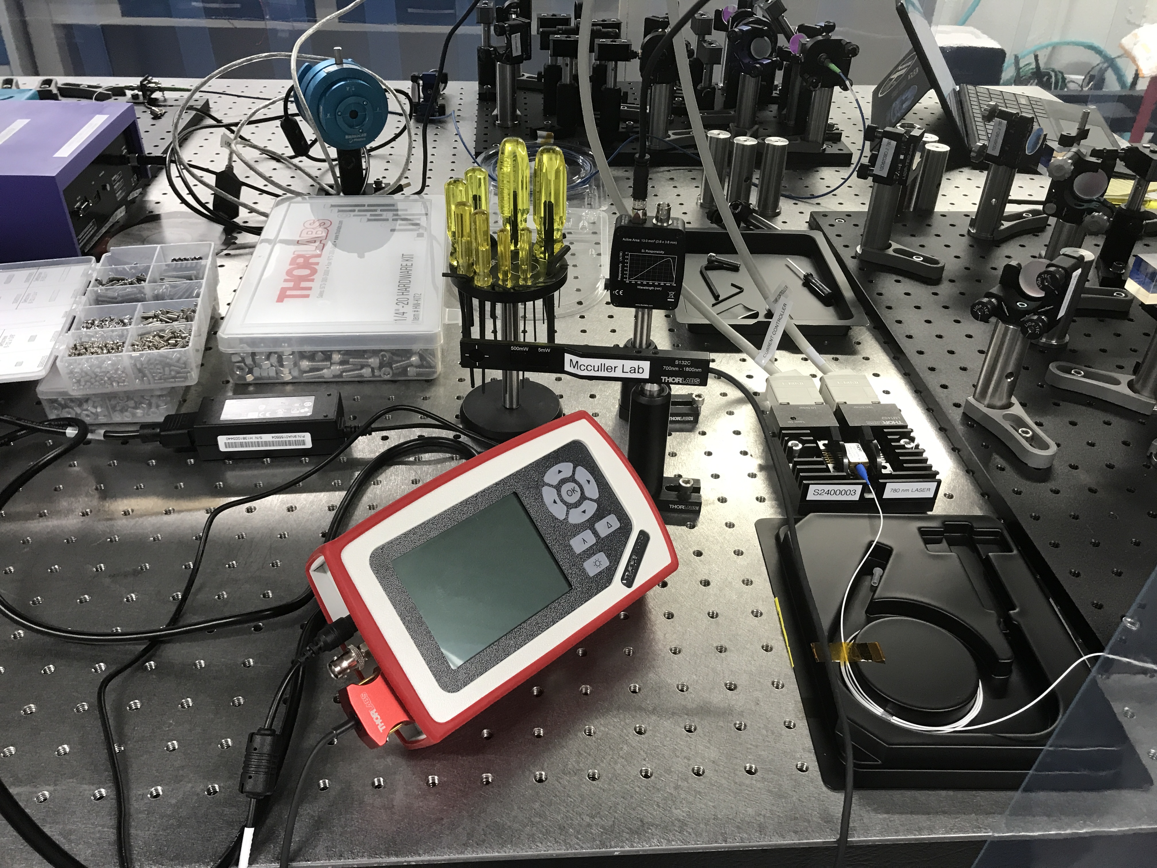
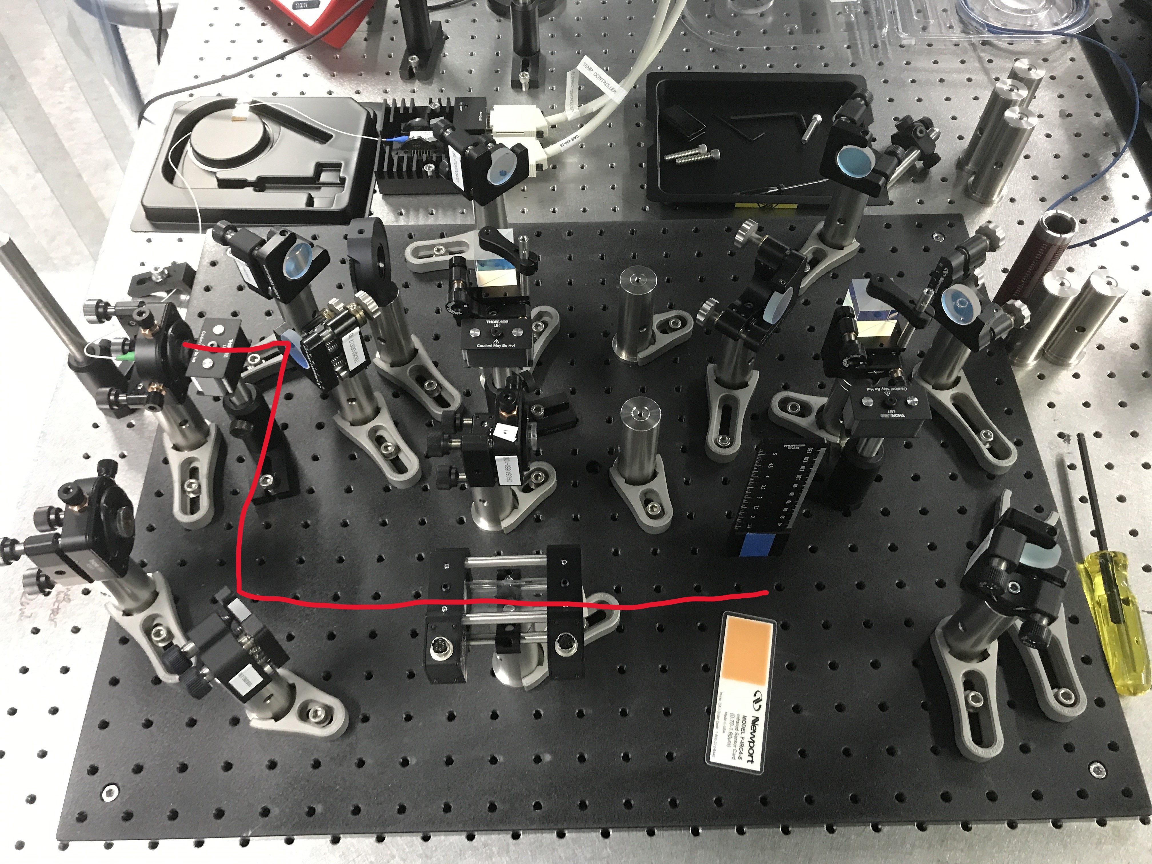
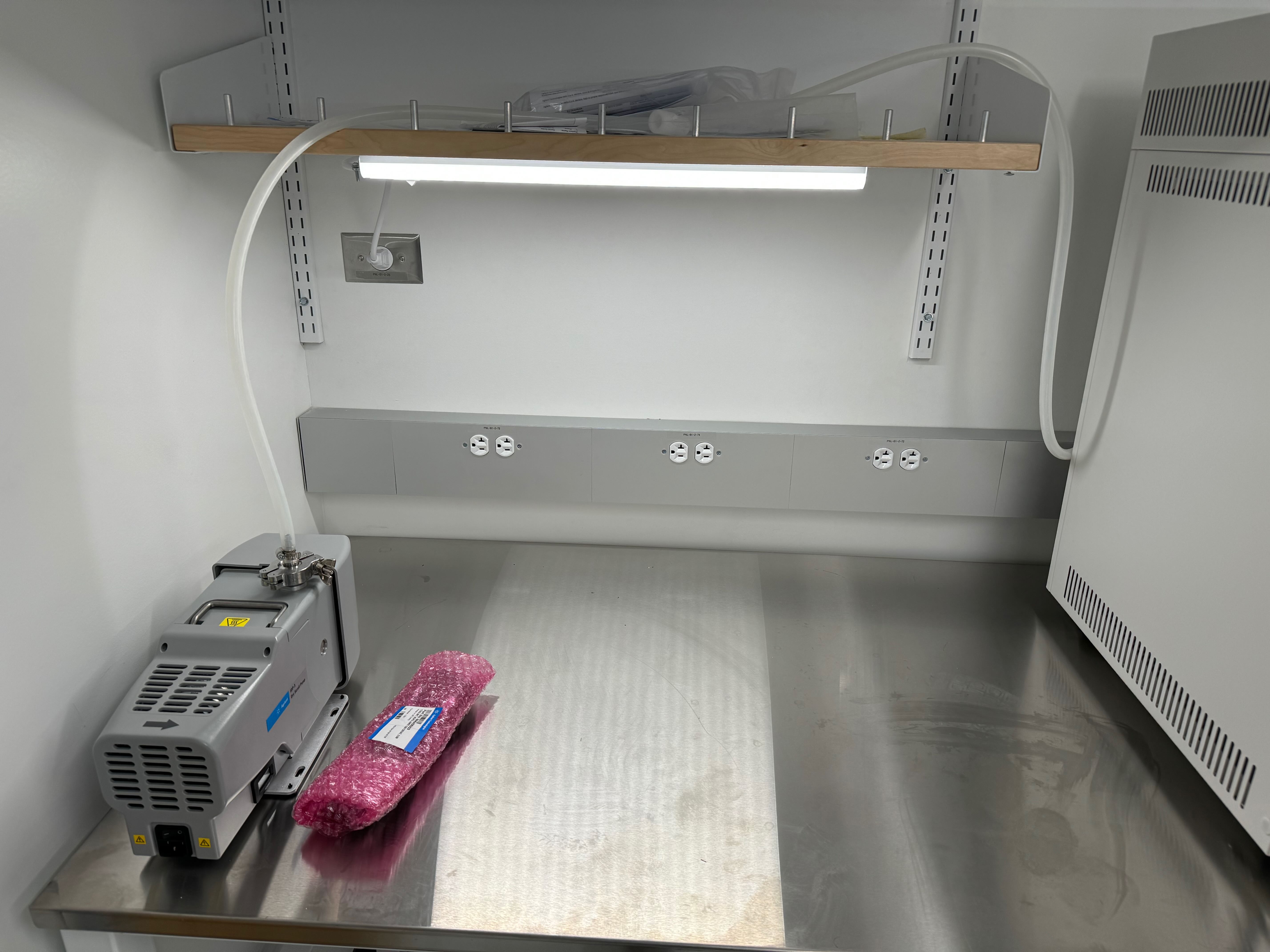
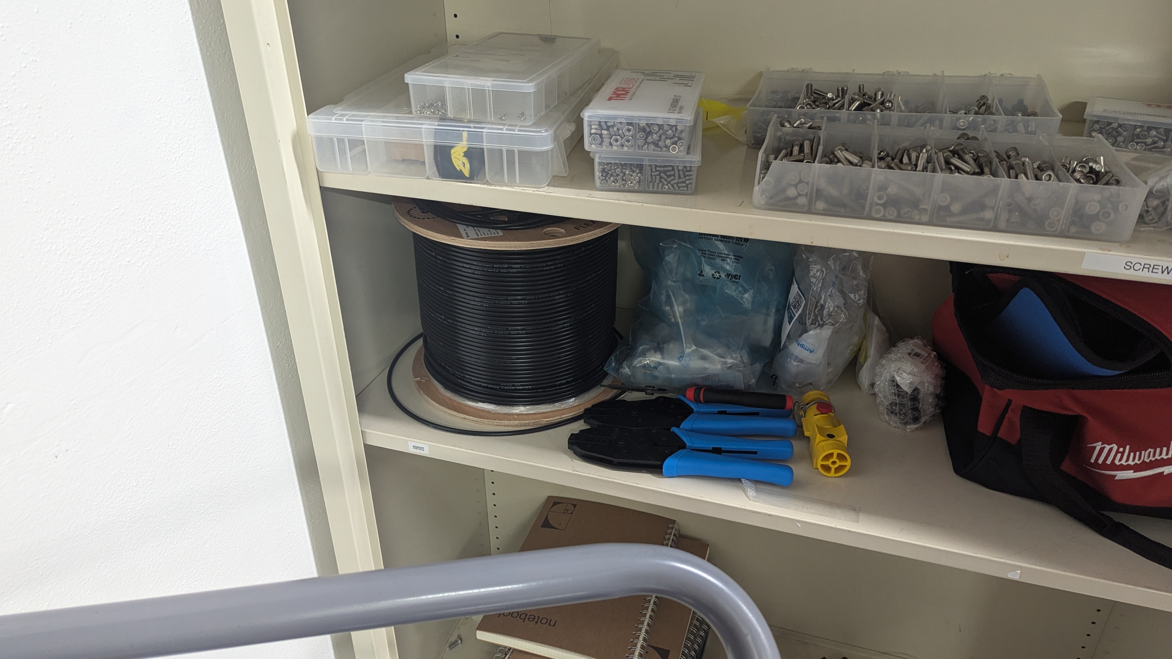
Location of tools to make homemade shielded BNC
Images attached to this report
Comments related to this report
This holds the record as the shortest logpost.
Put quite a keenly useful log!
There is a wire spooler in the new makerspace, that the cable spool should eventually go on. I also have a couple more wire stripping tools to collect.